

Oral treatment supplementary instrument
A technology of oral treatment and auxiliary devices, which is applied in medical science, dentistry, etc., can solve the problems of poor patient compliance and uncomfortable taste, and achieve the effect of avoiding pollution and large opening
- Summary
- Abstract
- Description
- Claims
- Application Information
AI Technical Summary
Problems solved by technology
Method used
Image

Examples
Embodiment Construction
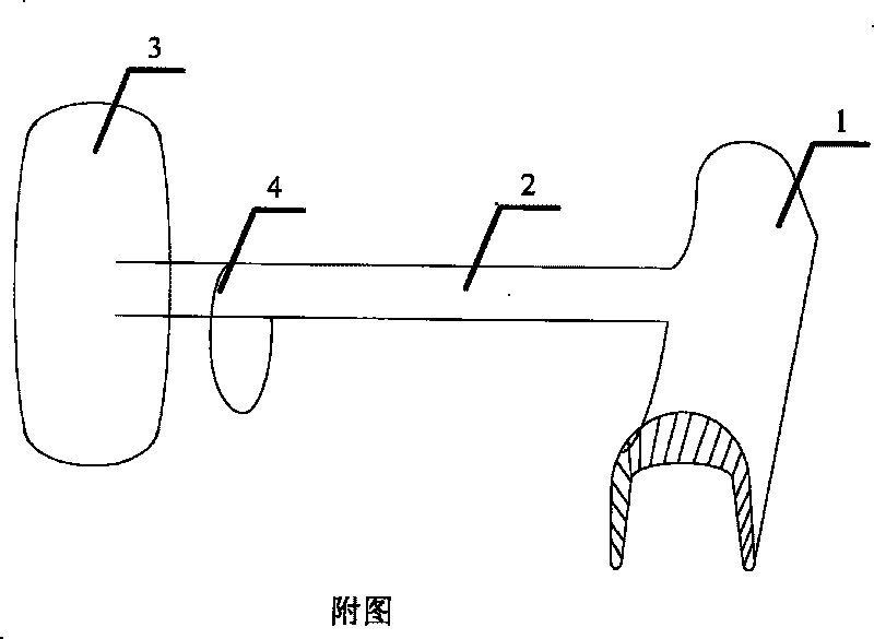
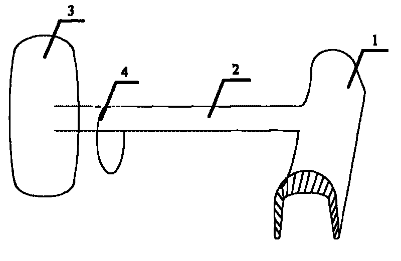
[0006] As shown in the accompanying drawings: the dental treatment aid includes a partial brace 1, a support rod 2, a cheek plate 3 and a movable retaining ring 4 on the support rod. Partial braces 1, made of elastic plastic. Covered on local teeth and gums, the surface and edges are smooth, the upper edge of the braces is thicker, and the side edges are thinner. One end of the support rod 2 is connected to the upper edge of the brace, and the other end is connected to the middle of the cheek plate. Flattened in shape with smooth edges. The cheek plate 3 is in the shape of a smooth oblate arc that fits with the shape of the buccal muscles. 4 sets of retaining rings are movable on the support rod and placed on the side edge of the tongue on the treatment side. One set of partial braces is placed on the contralateral tooth and gum on the treatment side, and the supporting rod 2 and the cheek plate 3 connected to it are stretched in a targeted manner through the retaining forc...
PUM
 Abstract
Description
Claims
Application Information