

Louver distribution of raising pneumatic stability
A technology of stability and layout, applied in the field of turbomachinery, can solve problems such as the potential limitation of mining
- Summary
- Abstract
- Description
- Claims
- Application Information
AI Technical Summary
Problems solved by technology
Method used
Image

Examples
Embodiment 1
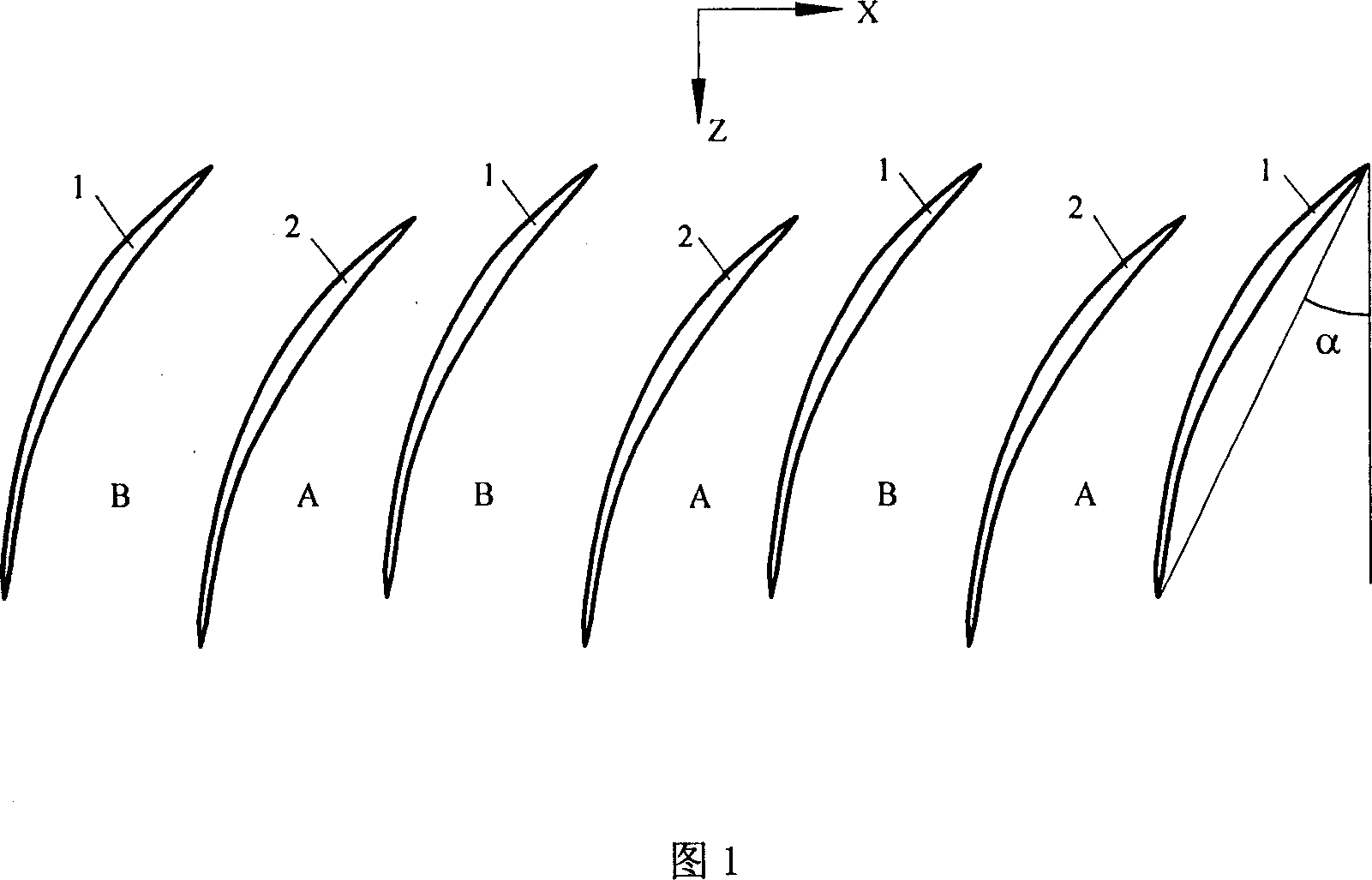
[0014] In this embodiment, the front edges of the same row of blades along the circumferential direction, that is, in the X direction, are arranged alternately in an axial direction, that is, in the Z direction.
[0015] The leading edge of blade 2 in the axial position moves backward relative to the leading edge of blade 1 in the normal position along the axis of the compressor for a certain distance, and the moving distance is 7% of the axial chord length of the blade, wherein the axial chord length is taken as the normal position The width of the blade in the axial direction. In this embodiment, the profile of the blade 2 at the backward position is exactly the same as that of the blade 1 at the normal position, and the installation angle changes to 0°.
Embodiment 2
[0017] In this embodiment, the front edges of the same row of blades along the circumferential direction, that is, in the X direction, are arranged alternately in an axial direction, that is, in the Z direction.
[0018] The leading edge of blade 2 in the axial position moves backward relative to the leading edge of blade 1 in the normal position along the axis of the compressor for a certain distance, and the moving distance is 13% of the axial chord length of the blade, wherein the axial chord length is taken as the normal position The width of the blade in the axial direction, and the blade 2 rotates 0.5° around the leading edge point toward the direction of the blade pot, that is, the installation angle defined by the axial Z direction is reduced by 0.5°. In this embodiment, the profile of the blade 2 in the backward position is exactly the same as that of the blade 1 in the normal position.
Embodiment 3
[0020] In this embodiment, the front edges of the same row of blades along the circumferential direction, that is, in the X direction, are arranged alternately in an axial direction, that is, in the Z direction.
[0021] The leading edge of blade 2 moves backward in the axial position relative to the leading edge of blade 1 in the normal position and moves backward for a certain distance along the axial direction of the compressor. The moving distance is 10% of the axial chord length of the blade, and the axial chord length is taken as the normal position The width of the blade in the axial direction, and the blade 2 rotates 3.0° around the leading edge point toward the direction of the blade pot, that is, the installation angle defined by the axial Z direction is reduced by 3.0°. In this embodiment, the profile of the blade 2 in the backward position is exactly the same as that of the blade 1 in the normal position.
PUM
 Abstract
Description
Claims
Application Information