Premixing burner arrangement for operating a combustion chamber in addition to a method for operating a combustion chamber

a technology of premixing burner and combustion chamber, which is applied in the direction of combustion types, combustion of lumps and pulverulent fuel, lighting and heating apparatus, etc., to achieve the effect of low burner pressure loss and increased aerodynamic stability of the inner backflow zon

Inactive Publication Date: 2011-03-01
ANSALDO ENERGIA SWITZERLAND AG
View PDF8 Cites 0 Cited by
  • Summary
  • Abstract
  • Description
  • Claims
  • Application Information

AI Technical Summary

Benefits of technology

[0012]A premixing burner is disclosed wherein, on the one hand, the aerodynamic stability of the inner backflow zone can be increased, particularly in the region of the forward stagnation point, without an appreciable additional burner pressure loss in this case having to be taken into account. Furthermore, a corresponding method for operating a combustion chamber can be disclosed, which is to serve both for avoiding the occurrence of thermoacoustic oscillations and for achieving the aim of as low a burner pressure loss as possible.
[0013]An exemplary premixing burner is based on the idea that the aerodynamic stability of the free inner backflow zone can be increased in that the swirl gradient of the swirl flow is increased locally upstream of the forming backflow zone in the flow direction. By the swirl gradient being increased only locally, that is to say along the axially propagating swirl flow within the premixing burner, it is appropriate to raise the swirl coefficient in the axial flow direction from an initial swirl coefficient to a higher swirl coefficient in a spatially limited manner and to lower it immediately thereafter to the initial swirl coefficient or to a swirl coefficient lower than the latter. In an exemplary embodiment, the overall burner pressure loss is increased only insignificantly, thus resulting in no or only very slight effects on the overall efficiency of a gas turbine.
[0016]On account of this convergent / divergent flow routing along the burner axis in the flow direction by the contour narrowing the flow cross section, the swirl gradient can be increased locally, as a result of which, in turn, the aerodynamic stability of the forming forward front of the backflow zone can be improved. Because of an unchanged burner contour at the burner outlet, especially since the contour is located upstream of the burner outlet, the burner pressure loss can be influenced only insignificantly. An impairment of the overall efficiency of a gas turbine can thereby be largely avoided.

Problems solved by technology

However, a lower swirl gradient implies a greater deflection at the stagnation point in the flow direction, possibly with disturbances occurring, and is conducive to the above-described formation of thermoacoustic instabilities.

Method used


Image

  • Premixing burner arrangement for operating a combustion chamber in addition to a method for operating a combustion chamber
  • Premixing burner arrangement for operating a combustion chamber in addition to a method for operating a combustion chamber
  • Premixing burner arrangement for operating a combustion chamber in addition to a method for operating a combustion chamber

Examples


Embodiment Construction

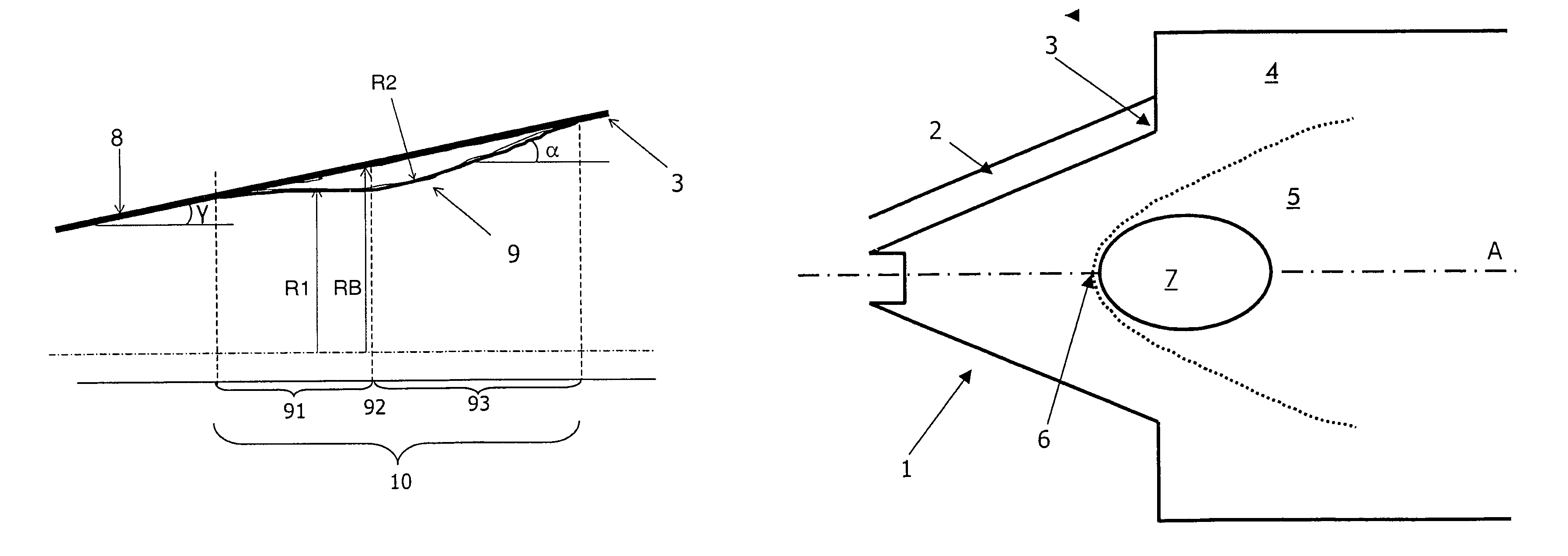
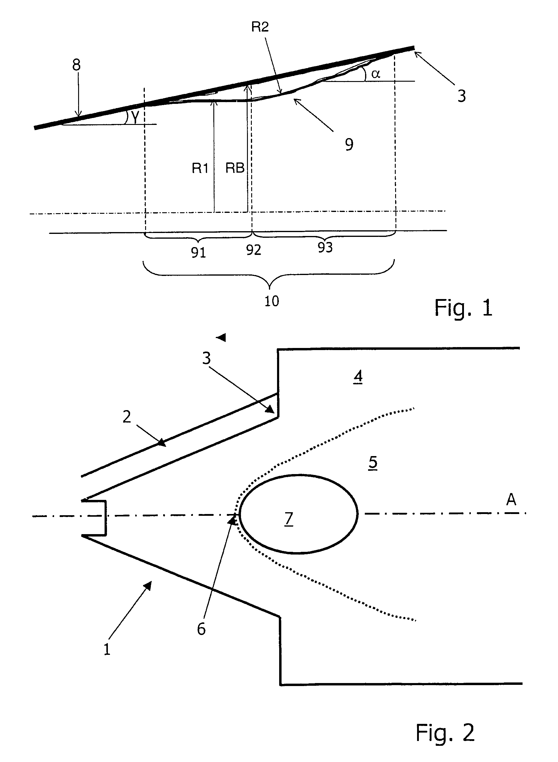
[0027]FIG. 1 shows a diagrammatic detail of a longitudinal section through a swirl generator of a double cone premixing burner with a burner wall 8 which with the burner axis A forms a cone half angle γ. A contour 9 narrowing the axial flow cross section is provided on the inside of the burner wall 8 upstream of the burner outlet 3. The contour 9 reduces the flow cross section longitudinally with respect to the burner axis A within a local region 10 in such a way that the shape and size of the burner outlet 3 are not impaired by the contour 9. The contour 9 has a first segment 91, by means of which the flow cross section is reduced continuously. The first segment 91 has adjoining it directly a second segment 92 which predetermines the smallest flow cross section. The second segment 92 is, for example, merely punctiform or linear. The region of the smallest flow cross section has adjoining it downstream a third segment 93 by means of which the flow cross section is widened again, for...


PUM


Abstract

A premixing burner is disclosed for operating a combustion chamber with a liquid and / or gaseous fuel, with a swirl generator for a combustion inflow air stream for forming a swirl flow, and with injection of fuel into the swirl flow. The swirl generator is adjacent to the combustion chamber indirectly via a mixing zone or directly, in each case via a burner outlet, a cross-sectional widening at the burner outlet being provided which, is discontinuous in the flow direction of the swirl flow and through which the swirl flow bursts open so as to form a backflow zone. A contour locally narrowing the flow cross section of the swirl generator or of the mixing zone in the flow direction can be provided upstream of the burner outlet.

Description

RELATED APPLICATIONS[0001]The present application claims priority under 35 U.S.C. §120 as a continuation of PCT / EP2005 / 050105, filed Jan. 12, 2005, and claims priority under 35 U.S.C. §119 to Swiss Patent Application No. 00072 / 04, filed Jan. 20, 2004, the disclosures of which are hereby incorporated by reference in their entireties.BACKGROUND[0002]1. Field[0003]A premixing burner and a method for operating a combustion chamber by means of a liquid and / or gaseous fuel are disclosed, with a swirl generator for a combustion inflow air stream for forming a swirl and with means for the injection of fuel into the swirl flow, the swirl generator being adjacent to the combustion chamber indirectly via a mixing zone or directly, in each case via a burner outlet, a cross-sectional widening at the burner outlet being provided, which is discontinuous in the flow direction of the swirl flow and through which the swirl flow bursts open so as to form a backflow zone.[0004]2. Background Information...

Claims


Application Information

Patent Timeline
Patent Type & Authority Patents(United States)
IPC IPC(8): F23R3/28F23C7/00F23D14/02
CPCF23C7/002F23D14/02F23C2900/07002F23D2209/20
Inventor FLOHR, PETERPASCHEREIT, CHRISTIAN OLIVER
Owner ANSALDO ENERGIA SWITZERLAND AG
Why Eureka
Try Eureka