
Dishware cleaning machine

A dishwashing machine and washing tank technology, applied in dishwashing machine/washing machine, dishwashing machine/rinsing-washing machine parts, dishwasher application, etc., can solve the problems of rising air humidity and user discomfort, etc. , to achieve the effect of good energy saving performance and convenient use

Inactive Publication Date: 2007-05-09
PANASONIC CORP
View PDF1 Cites 10 Cited by
  • Summary
  • Abstract
  • Description
  • Claims
  • Application Information

AI Technical Summary

Problems solved by technology

[0008] However, in the existing dishwasher with the above-mentioned structure, all the heat for heating the washing water is the heat generated by the heater 108 when washing various types of tableware 107, and only the consumed power is used as heat.
In addition, since all the water vapor generated when the various tableware 107 is dried is exhausted outside the machine, the humidity of the indoor air in the kitchen where the dishwasher body 101 is installed will increase, causing the user to feel uncomfortable.

Method used


Image

  • Dishware cleaning machine
  • Dishware cleaning machine
  • Dishware cleaning machine

Examples


Embodiment 1

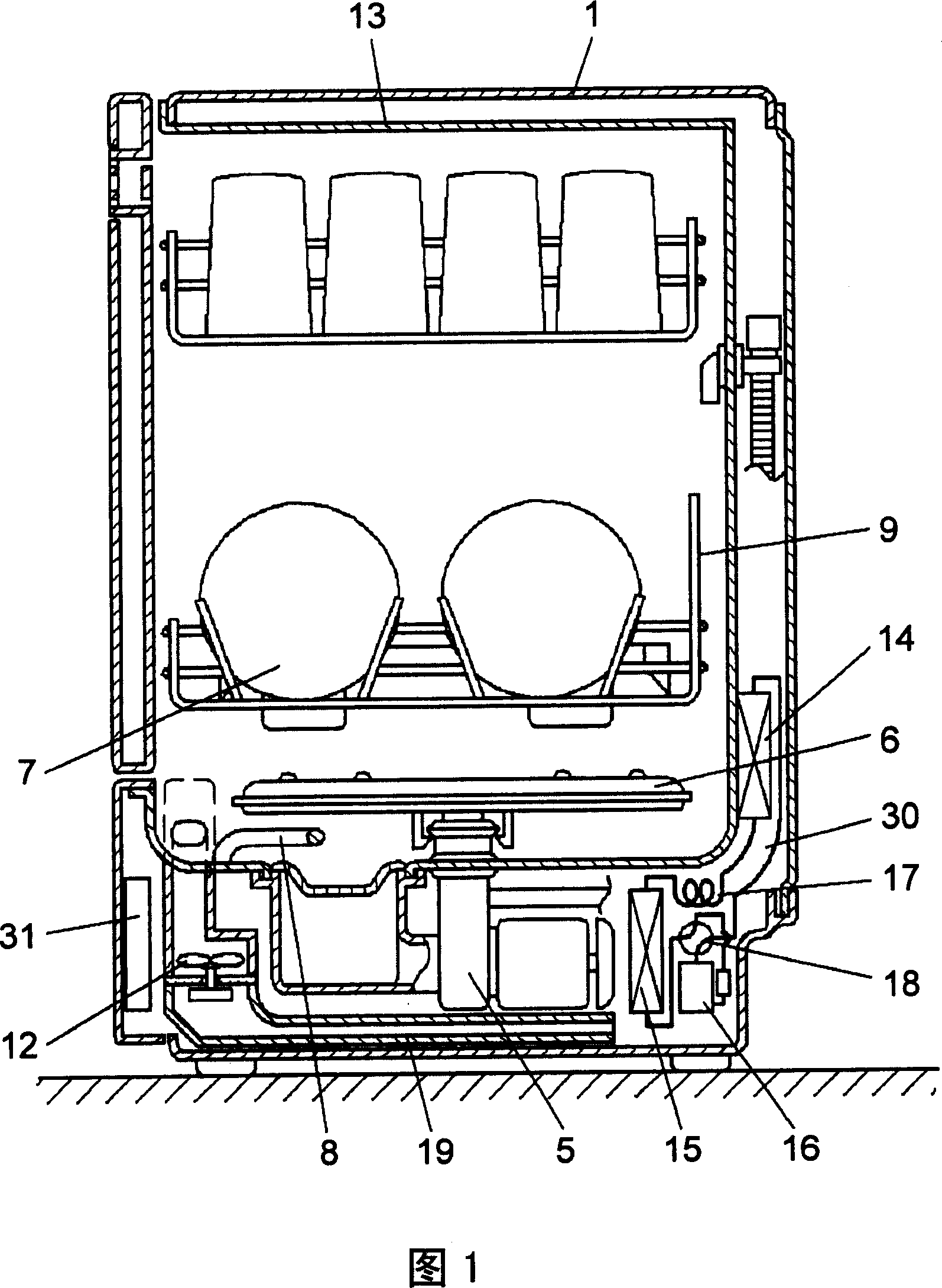
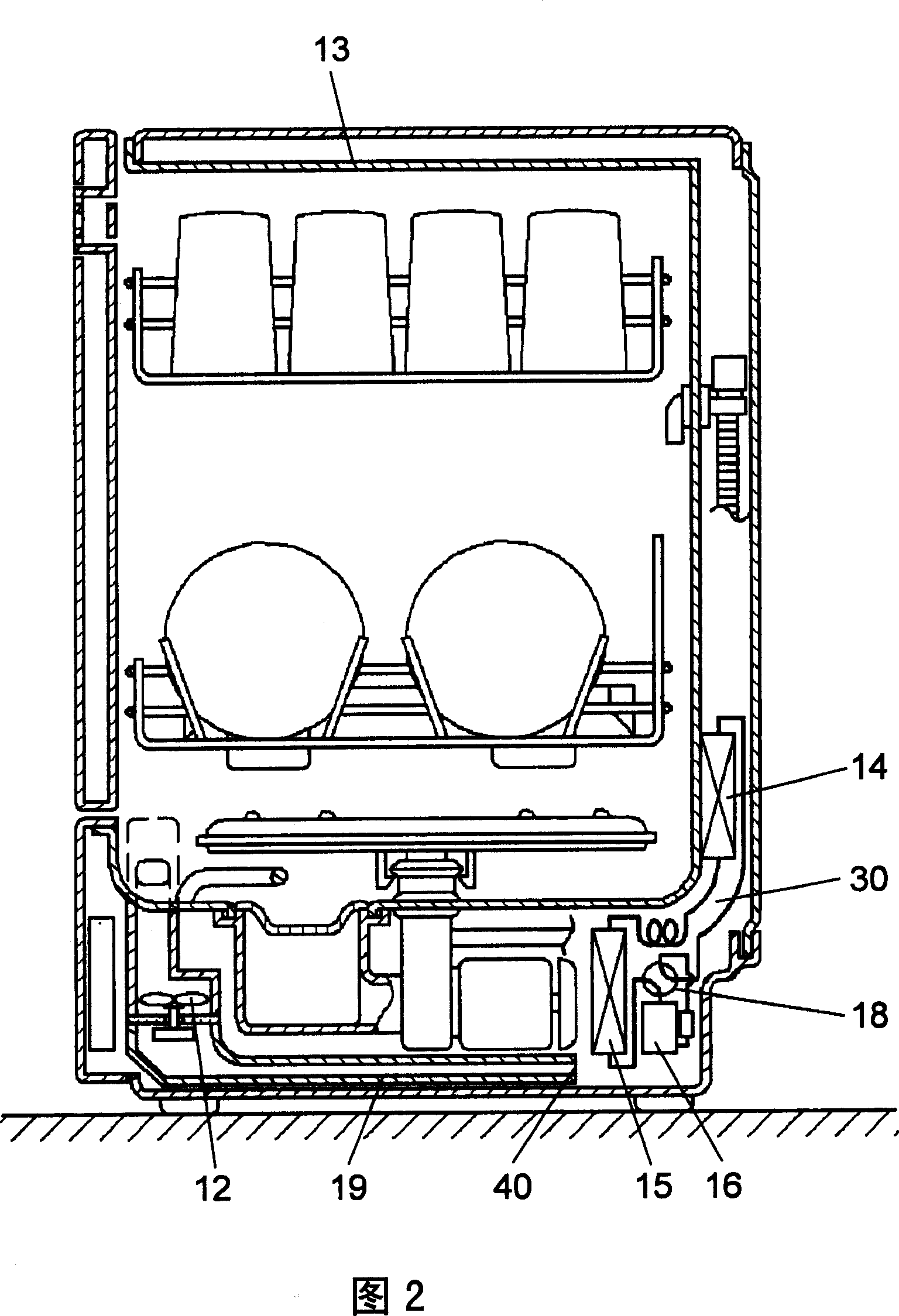
[0019] Fig. 1 is a side sectional view of the dishwasher in embodiment 1 of the present invention in the cleaning process, and Fig. 2 is a side sectional view of the dishwasher in the drying process.

[0020] First, the main components of the dishwasher in Embodiment 1 will be described using FIGS. 1 and 2 . The dishwashing machine of the present embodiment 1 includes: a cleaning tank 13; a heat pump unit 30; a control unit 31 for sequentially controlling a series of operation strokes such as cleaning, rinsing, heating and rinsing, and drying; The heat exchanger 14 for exchanging heat with the cleaning water in the tank 13 . The control unit 31 performs switching control on the heat exchanger 14, so that it becomes a condenser in at least one of the cleaning and heating rinsing strokes, and becomes an evaporator in the drying stroke.

[0021] With such a configuration, the heat pump unit 30 can transfer the surrounding heat to the washing water during the washing and heating ...

Embodiment 2

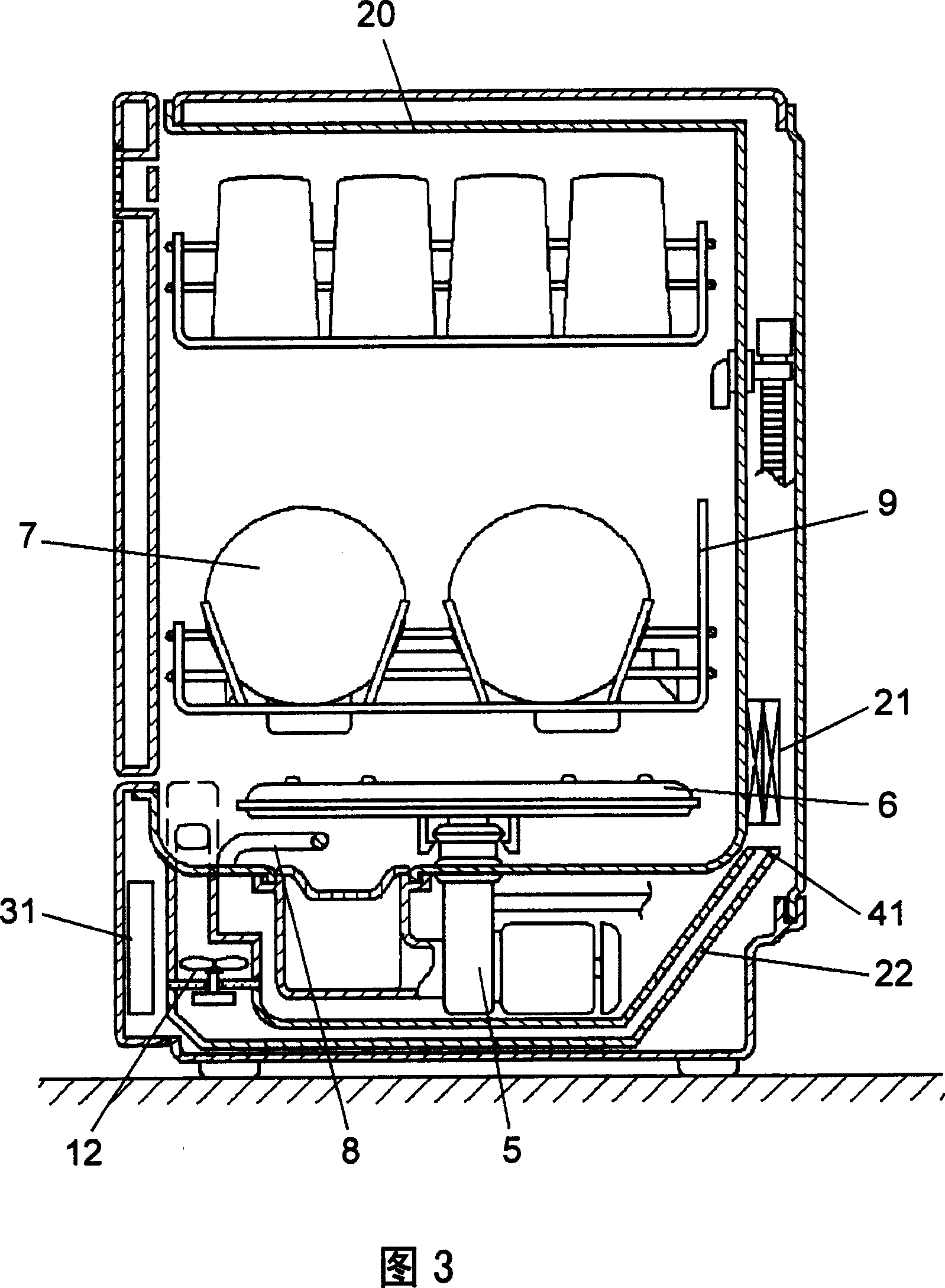
[0031] Fig. 3 is a side sectional view of the dishwasher shown in Embodiment 2 of the present invention. As shown in FIG. 3 , the dishwasher of the second embodiment is provided with a Peltier element 21 in contact with the outside of the rear wall of the washing tank 20 , instead of the heat pump unit 30 in the first embodiment. In addition, since other components in the dishwasher are the same as those in Embodiment 1, description thereof will be omitted here.

[0032] Next, the operation and function of the dishwasher in the second embodiment having the above-mentioned structure will be described. Before washing the tableware, the user first loads various tableware 7 into the tableware basket 9 , and then loads the tableware basket 9 into the cleaning tank 20 . After the dish washer starts to work, the washing pump 5 is driven, and the pressurized washing water is sprayed from the washing nozzle 6 to various tableware 7 .

[0033] In the washing process and the heating an...


PUM


Abstract

A dinnerware washer comprises: a washing tank; a heat pump unit; a control unit for controlling a series of process including washing, flushing, heat flushing, drying process etc; and a first heat exchanger composing the heat pump and exchanging heat with the washing water in the washing tank, wherein, the control unit switch controls the first heat exchanger making the heat exchanger work as a condenser in at least one process of washing process and heat flushing process, and work as an evaporator in drying process. A dinnerware washer having good power saving performance and convenient usage is provided by utilizing this structure.

Description

field of invention [0001] The present invention relates to a dishwasher for washing various kinds of dishes by spraying washing water from a washing nozzle. Background technique [0002] Fig. 4 is a side cross-sectional view of a conventional dishwasher, showing a configuration example of such a conventional dishwasher. The constitution of such a conventional dishwasher will be described below. [0003] As shown in FIG. 4 , a cleaning tank 102 is provided inside the body 10 of the dishwasher, and a drain hole 103 is provided at the bottom of the cleaning tank 102 . A cleaning pump 105 is provided in the pump chamber communicating with this drain hole 103 . The cleaning pump 105 is driven by the motor 104 , and the cleaning water circulates inside the cleaning tank 102 under the action of the cleaning pump 105 . [0004] The path through which the washing water circulates is as follows. First, the cleaning water is sucked by the cleaning pump 105 from the drainage hole 10...

Claims


Application Information

Patent Timeline
IPC IPC(8): A47L15/42
CPCY02B40/44Y02B40/00A47L15/4291A47L15/46A47L15/483
Inventor 上崎昌芳角谷胜彦
Owner PANASONIC CORP
Learn More