Hollow component

A technology of hollow components and cavities, which is applied to building components, building structures, floor slabs, etc., can solve the problems of increasing the production cost of thin-walled boxes, the construction cost of cast-in-place reinforced concrete hollow slabs, large space occupation, and high transportation costs

Inactive Publication Date: 2007-05-09
湖南邱则有专利战略策划有限公司
View PDF2 Cites 0 Cited by
  • Summary
  • Abstract
  • Description
  • Claims
  • Application Information

AI Technical Summary

Problems solved by technology

However, this kind of thin-walled box formwork member, as an integral thin-walled box member, takes up a lot of space during transportation, the quantity of each transportation is small, and the transportation cost is high, w...

Method used


Image

  • Hollow component
  • Hollow component
  • Hollow component

Examples


Embodiment Construction

[0042] The present invention will be further described below in conjunction with the drawings and embodiments.

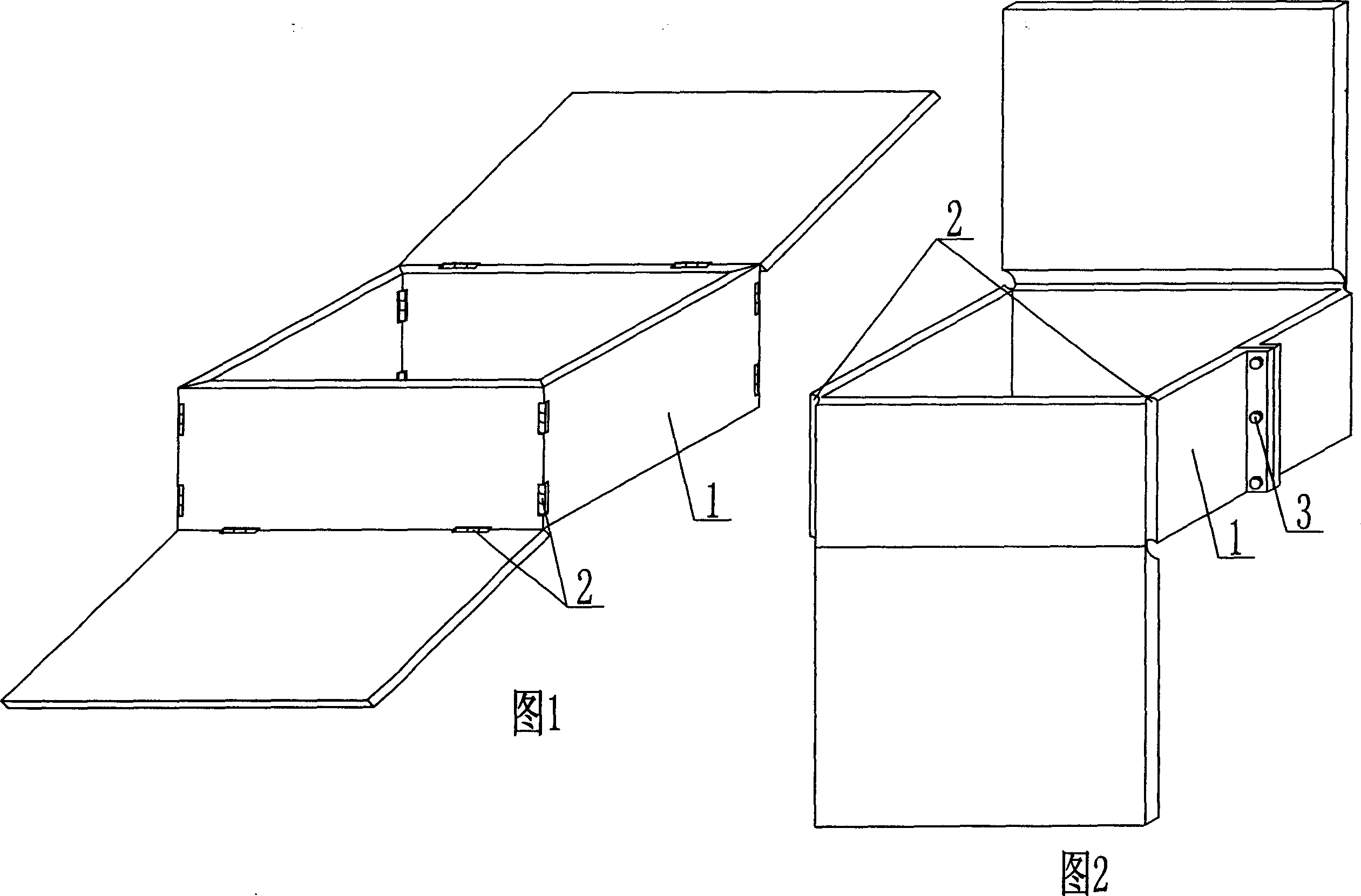
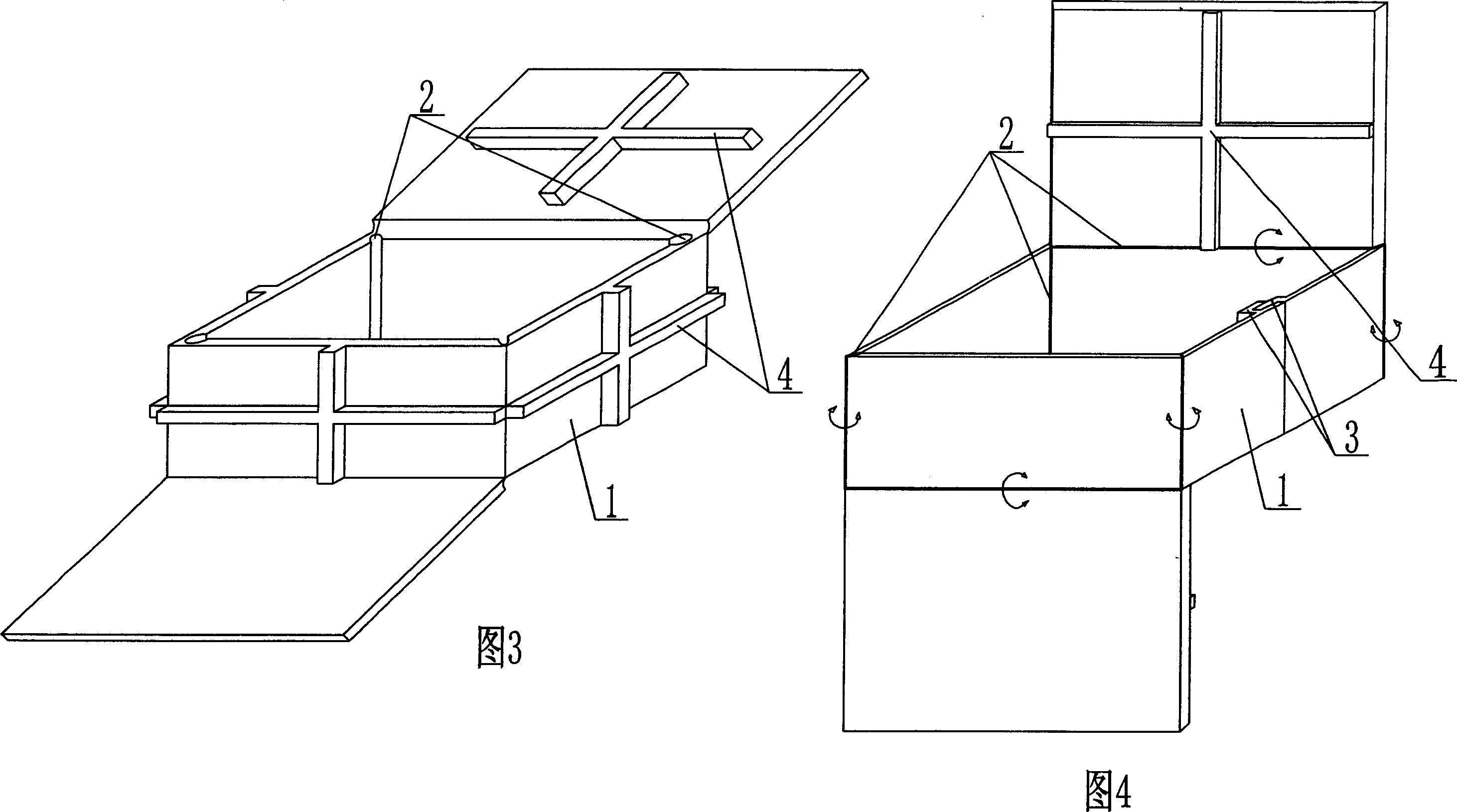
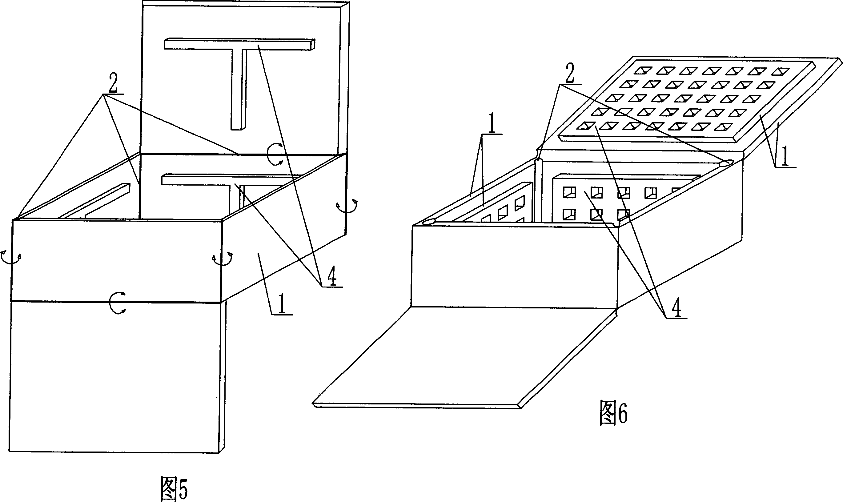
[0043] As shown in the accompanying drawings, the present invention includes a polyhedral outer wall 1, which encloses the outer wall 1 to form a hollow polyhedron, and is characterized in that the intersection of the outer wall 1 is a hinge 2, and the polyhedral outer wall 1 can be folded into a basin shape and can be spread out or Single-layer or / and double-layer plate-shaped, at least one ring of outer wall 1 is joined by joining members 3 longitudinally facing the joining body. As shown in Figure 2, the hollow member includes a polyhedral outer wall 1. The outer wall 1 is enclosed to form a hollow polyhedron. The intersection of the outer wall 1 is a hinge 2. The polyhedral outer wall 1 can be folded into a basin, spread out or single-layer In the shape of a double-layer plate, the outer wall 1 is longitudinally joined to the joint 3 of the joint body.

[0044]The p...


PUM


Abstract

The present invention relates to a hollow member. It includes a polyhedral external wall; said polyhedral external wall can be formed into a hollow cavity polyhedron. It is characterized by that the crossed position of the described external wall surface is a hinge joint, said polyhedral external wall can be folded and can be made into a box form, and can be spread to form single-layer or double-layer plate-sheet form. Said hollow member can be used for in-situ cast various hollow plates, hollow floor, roof, foundation bedplate, wall body and open-web bridge, etc.

Description

(1) Technical field [0001] The invention relates to a hollow member. (2) Background technology [0002] At present, in the prior art, the cast-in-situ reinforced concrete hollow slab hole-forming component is a permanent core mold, such as paper tube, plastic tube, metal corrugated tube, hollow mold shell, core mold light material, etc. These tubular core molds or hollow components are mainly considered to be evacuated to reduce the weight of the hollow slab. For example, the applicant applied for a patent number ZL99249798.1 on November 29, 1999, a utility model patent named "fiber-reinforced thin-walled member for reinforced concrete filling", which discloses a thin-walled formwork member including an upper plate, The surrounding side walls, the lower bottom, the upper plate, the surrounding side walls and the lower bottom enclose a polyhedral cavity. Another example is the application number 01140106.0 and the publication number CN1356442 that the applicant filed on November 2...

Claims


Application Information

Patent Timeline
IPC IPC(8): E04B5/16E04B5/36E04C1/00
Inventor 邱则有
Owner 湖南邱则有专利战略策划有限公司
Why Eureka
Try Eureka