Sensor of dust concentration

A technology of dust concentration and sensor, which is applied in the direction of scientific instruments, measuring devices, suspension and porous material analysis, etc. It can solve the problems that the dust concentration instrument cannot be displayed in real time and continuous monitoring, etc., and achieves the reduction of user workload, compact structure, and good appearance. beautiful effect

Inactive Publication Date: 2007-05-09
南京富邺科技有限公司
View PDF0 Cites 10 Cited by
  • Summary
  • Abstract
  • Description
  • Claims
  • Application Information

AI Technical Summary

Problems solved by technology

[0003] The purpose of the present invention is to overcome the problem that the current dust concentration instrument cannot be displayed and continuously monitored, and provides a dust concentration sensor, which can measure and display the dust concentration in real time, and convert it into a frequency signal output for use in a safety monitoring system. Able to work continuously for a long time under dusty environmental conditions

Method used


Image

  • Sensor of dust concentration
  • Sensor of dust concentration

Examples


Embodiment Construction

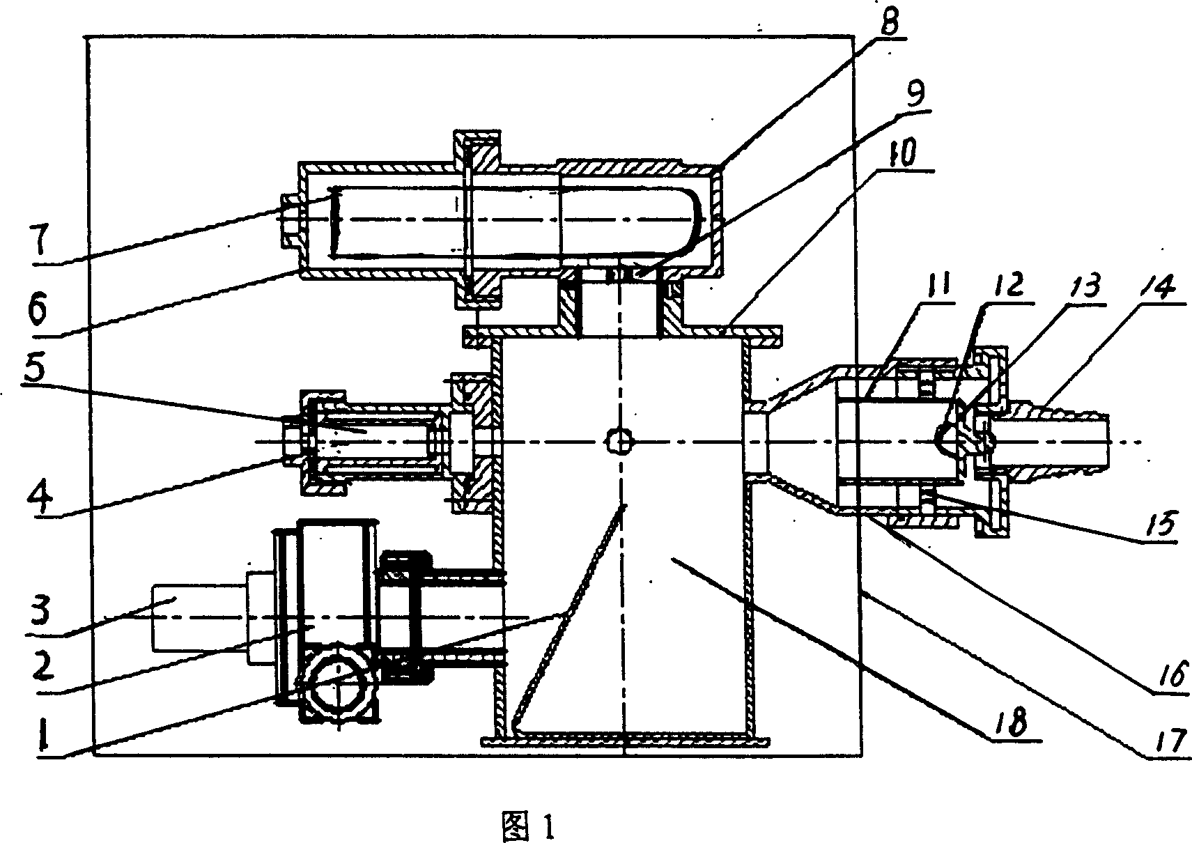
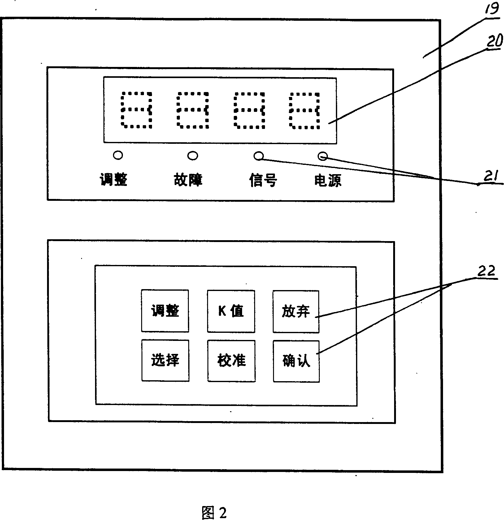
[0024] Referring to accompanying drawings 1 and 2, the structure of the dust concentration sensor consists of a housing 17, a dust sampling head, a dust chamber 18, a fan 2, and a photoelectric receiving device. The dust chamber 18 is installed in the shell 17, the dust sampling head is arranged on one side of the dust chamber 18, the fan 2 is installed on the other side of the dust chamber, and the photoelectric receiving device is arranged on the top of the dust chamber 18. The front side of the casing 17 is provided with a display operation panel 19 , and the display operation panel 19 is provided with a digital display 20 , a working status indicator light 21 , and function operation buttons 22 .

[0025] The dust sampling head includes an air inlet nozzle 14, a sampling pipe 16, a light source 12, and a separator 11. The air inlet nozzle 14 is mounted on the front end of the sampling pipe 16, the sampling pipe 16 is fixed on the upper side of the dust chamber 18, and the s...


PUM


Abstract

A transducer of dust concentration is prepared as setting dust chamber in shell, arranging dust sampling head at one side of dust chamber, arranging fan at another side of dust chamber and setting photoelectric receiving unit at top of dust chamber.

Description

technical field [0001] The dust concentration sensor of the present invention relates to a sensor that continuously monitors the dust concentration for a long time and displays the dust concentration value immediately, and converts it into a frequency signal output at the same time. Monitoring, public places and other environmental monitoring. Background technique [0002] At present, for the measurement of dust concentration, dust samplers and direct-reading dust detectors are mainly used. The former uses the principle of filter membrane weighing method: a certain volume of dusty air is extracted, and the dust is captured on the filter membrane. According to the increased dust mass on the filter membrane, the dust mass concentration in the unit volume of air is calculated by using the formula, which has The operation is troublesome, and the dust concentration value can only be obtained through calculation; the latter uses indirect methods such as light scattering, β source...

Claims


Application Information

Patent Timeline
IPC IPC(8): G01N15/06G01N21/53
Inventor 孙强孙超
Owner 南京富邺科技有限公司
Why Eureka
Try Eureka