Lens installation mechanism, and installation method, as well as method for adjusting inclination and focusing plane of sensor

A technology of installation mechanism and installation method, which is applied in the direction of installation, camera body, instrument, etc., and can solve the problems of uneven thickness of solder or adhesive, not being truly parallel, etc.

Inactive Publication Date: 2007-05-09
SONY TAIWAN
View PDF0 Cites 21 Cited by
  • Summary
  • Abstract
  • Description
  • Claims
  • Application Information

AI Technical Summary

Problems solved by technology

[0004] In addition, because the sensor 12 is fixed on the sensor fixing platform 16 by welding or bonding, therefore, the sensor 12 and the sensor fixing platform 16 may warp due to the uneven thickness of the solder or the adhesive, so that the two are not connected. It is really parallel, so whether the optical axis of the lens is really perpendicular to the sensor surface still needs to be considered

Method used


Image

  • Lens installation mechanism, and installation method, as well as method for adjusting inclination and focusing plane of sensor
  • Lens installation mechanism, and installation method, as well as method for adjusting inclination and focusing plane of sensor
  • Lens installation mechanism, and installation method, as well as method for adjusting inclination and focusing plane of sensor

Examples


Embodiment Construction

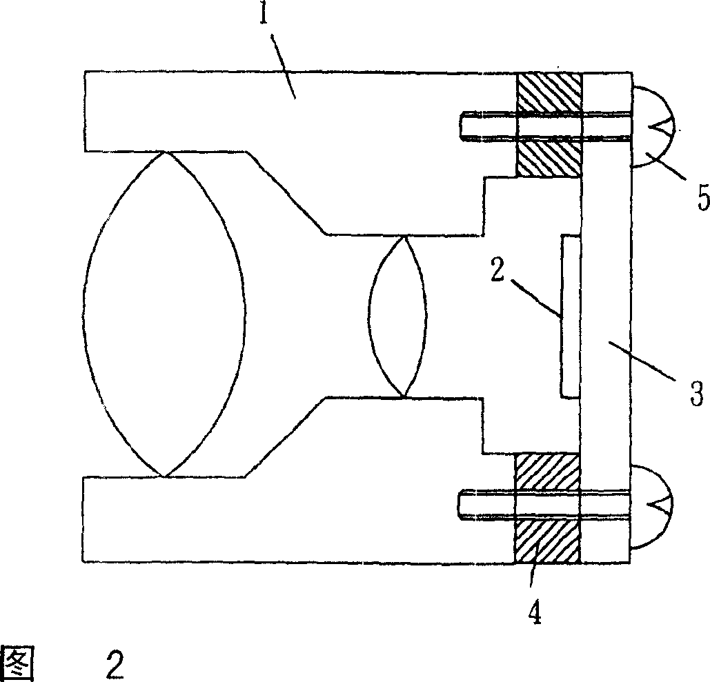
[0024] One embodiment of the present invention is conceptually shown in FIG. 2 . 2 is a cross-sectional view of a lens mounting mechanism using an elastic material according to an embodiment of the present invention.

[0025] In FIG. 2 , the sensor 2 is fixed on the substrate 3 by welding or bonding. A circle of rubber 4 is clamped between the lens 1 and the base plate 3, and is tightened and fixed by screws 5 passing through. The contact surface between the lens 1 and the rubber 4 and the contact surface between the rubber 4 and the substrate 3 are in a light-tight and always in close contact state.

[0026] Next, in the lens mounting mechanism using an elastic material of the present invention, the method of adjusting the sensor tilt and the method of adjusting the focus plane will be described using examples.

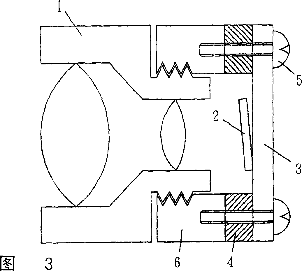
[0027] 3 to 7 are adjustment diagrams of sensor tilt and focus plane according to an embodiment of the present invention.

[0028] In FIG. 3 , the lens holder 6 a...


PUM


Abstract

A method for erecting lens cone includes welding or binding transducer on base plate, sandwiching a rubber ring between lens cone and base plate and using screw to fasten them, setting contact surface between lens cone and rubber and contact surface between rubber and base plate to be state of non-transparently seal-jointed always, enabling to regulate verticality of light axle on transducer to light axle on lens cone by adjusting various screws.

Description

technical field [0001] The present invention relates to a method for adjusting the perpendicularity between the optical axis of a lens and the surface of an optical sensor in a digital camera, and more particularly, to provide a lens mounting mechanism using elastic materials that does not require a light-shielding adhesive and has fewer parts , a lens installation method using elastic materials, a sensor tilt adjustment method, and a focusing plane adjustment method. Background technique [0002] Fig. 1 shows the installation method of the existing lens installation mechanism. The installation method of the mechanism shown in Figure 1, first, the sensor 12 is fixed on the sensor fixing platform 16 by welding or bonding, and it is supported and fixed by screws 15 and springs 14, and adjusted by tightening and loosening the screws 15 The sensor 12 is positioned such that the sensor surface is parallel to the lens fixing member 13 . Then, the lens 11 is bonded to the lens fi...

Claims


Application Information

Patent Timeline
Patent Type & Authority Applications(China)
IPC IPC(8): G03B17/12G02B7/02G03B5/00G02B7/04
Inventor 泷上耕太郎梅村刚土持诚
Owner SONY TAIWAN
Why Eureka
Try Eureka