Relay terminal device of circuit breaker

A technology for relay terminals and circuit breakers, which is applied in the direction of circuit breaker parts, switch terminals/connections, protective switch terminals/connections, etc. Solve problems such as terminal shape and size restrictions, and achieve the effect of convenient wiring work

Inactive Publication Date: 2010-05-12
FUJI ELECTRIC FA COMPONENTS & SYST CO LTD
View PDF2 Cites 0 Cited by
  • Summary
  • Abstract
  • Description
  • Claims
  • Application Information

AI Technical Summary

Problems solved by technology

Therefore, in order to connect the electric wire 5 to the terminal plate 6b of the terminal block 6, a large tightening force is required, and if the tightening of the terminal screw 6d is insufficient, the above-mentioned failure of pulling out the electric wire may occur.
[0008] Therefore, in order to avoid such failures and ensure the reliability of wiring, it is considered to use a round crimp terminal on the wire 5 to prevent the wire from being pulled out. Then, set the Figure 7 The box-shaped terminal connector 6c on the terminal block is dedicated to the wire harness and is not suitable for the connection of the round crimping terminal. Therefore, when connecting the round crimping terminal to the terminal block 6, it is necessary to temporarily The cover and terminal screw 6d are removed from the insulating frame 6a of the terminal block 6, and then the circular crimping terminal fixed on the core wire 5a of the electric wire 5 is inserted into the terminal screw 6d and tightened again. It takes a long time to work on wires. Moreover, since the terminal block 6 is made exclusively for the connection of wire harnesses, the shape and size of the usable round crimp terminals are limited.

Method used


Image

  • Relay terminal device of circuit breaker
  • Relay terminal device of circuit breaker
  • Relay terminal device of circuit breaker

Examples


Embodiment Construction

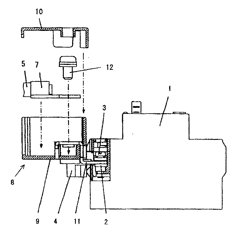
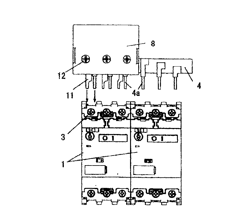
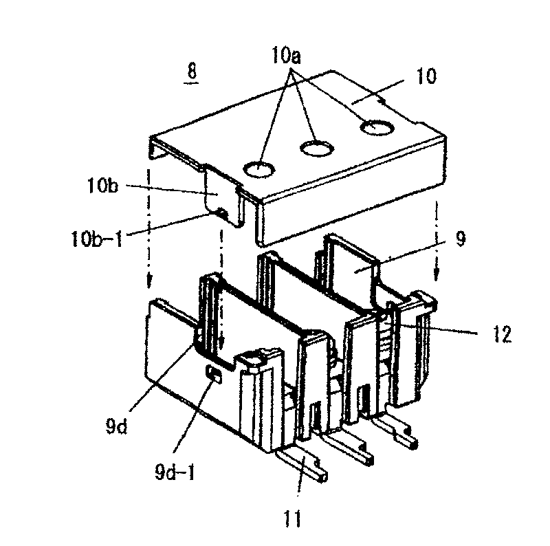
[0026] Below, according to Figure 1 to Figure 6 The shown examples illustrate the implementation of the present invention. in, figure 1 It is an exploded sectional view of the relay terminal block externally installed on the circuit breaker, figure 2 It is a plan view of the arrangement when the relay terminal block is connected to the circuit breaker, image 3 It is an exploded perspective view of the relay terminal block, Figure 4 is the detailed structural diagram of the box-shaped enclosure, Figure 5 It is a detailed structural diagram of the upper cover, Image 6 is a detailed structural diagram of the terminal board, and in addition, in the diagram of the embodiment, for the Figure 7 Corresponding components are assigned the same reference numerals, and descriptions thereof are omitted.

[0027] First, in figure 1 Among them, the circular crimping terminal 7 is attached to the electric wire 5 (rubber insulated flexible cable) arranged in a detour in the pane...


PUM


Abstract

The present invention provides a relay terminal device of circuit breaker, which is disposed on the main circuit terminal of the circuit breaker, for connecting the wire with circular press joining terminal from outside, and includes: an insulation frame combined by a box shape shell and a top cover body, wherein, the shell inner of said box shape shell is separated by interphase septa, and wire insert holes corresponding respectively to the main circuit are disposed in the front, and operation holes of terminal bolt are disposed on the top of the cover body, the cover body covers the top of the box shape shell and can be assembled / unassembled and locked with it; terminal plate of each phase fixed in the box shape shell inner and its end extrudes from the shell towards the back; and terminal bolts disposed on the terminal plate clamping the circular press joining terminal of the wire inserted into the box shape shell between the box shape shell and the terminal plate for fixed connection.

Description

technical field [0001] The present invention relates to a relay terminal device which is suitable for a wiring circuit breaker equipped in a distribution board, a power distribution board, etc., and which is externally installed on a power supply side terminal of the circuit breaker to connect electric wires from a power distribution system. Background technique [0002] As relay terminal devices used for connecting electric wires (such as rubber insulated flexible cables) of the power distribution system to the above-mentioned circuit breakers, there are known relay terminal devices corresponding to U, V, and W phases of the main circuit. a box-shaped terminal connector; and a terminal block (attachment to a circuit breaker) for wire connection in which a terminal board connected between the terminal connector and a main circuit terminal of a circuit breaker is installed in an insulating frame (resin case) (For example, refer to Patent Document 1). [0003] On the other ha...

Claims


Application Information

Patent Timeline
Patent Type & Authority Patents(China)
IPC IPC(8): H01H71/08H01H73/20
Inventor 川田久夫清水源广永广勇
Owner FUJI ELECTRIC FA COMPONENTS & SYST CO LTD
Why Eureka
Try Eureka