Placement system for a flying kite-type wind-attacked element in a wind-powered watercraft

A kite-style and component technology, which is applied in the field of opening systems to achieve the effect of small flight characteristics and simplified control

Inactive Publication Date: 2007-05-23
SKYSAILS GMBH & CO KG
View PDF0 Cites 18 Cited by
  • Summary
  • Abstract
  • Description
  • Claims
  • Application Information

AI Technical Summary

Problems solved by technology

[0003] A disadvantage of this deployment system, which is only outlined in the known literature and is not fully deployed, is that the deployment of the element on which wind acts must be achieved by means of an additional auxiliary drive in the form of a parachute
In addition, no measures are seen that would also allow for a more reliable protection of the larger windward elements

Method used


Image

  • Placement system for a flying kite-type wind-attacked element in a wind-powered watercraft
  • Placement system for a flying kite-type wind-attacked element in a wind-powered watercraft
  • Placement system for a flying kite-type wind-attacked element in a wind-powered watercraft

Examples


Embodiment Construction

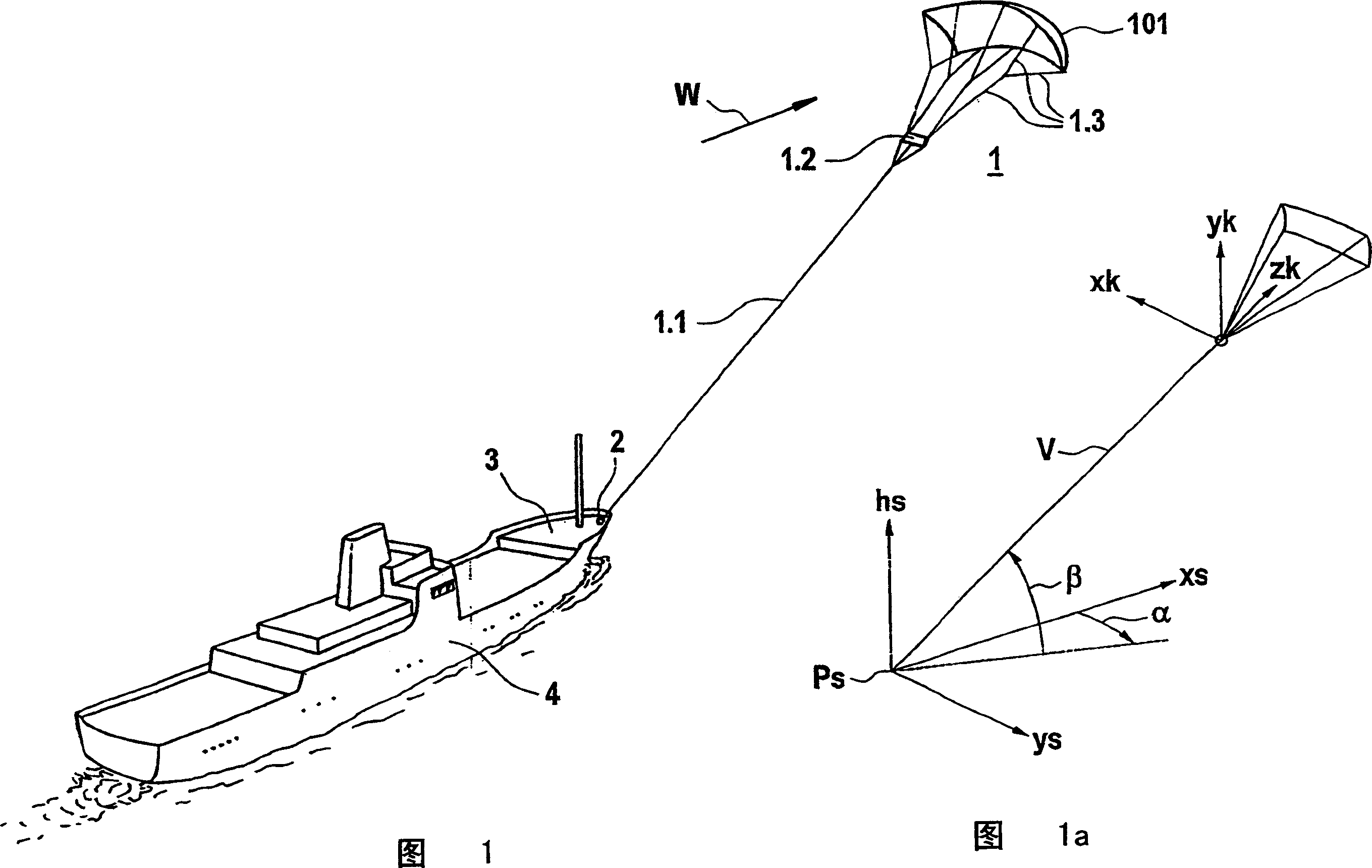
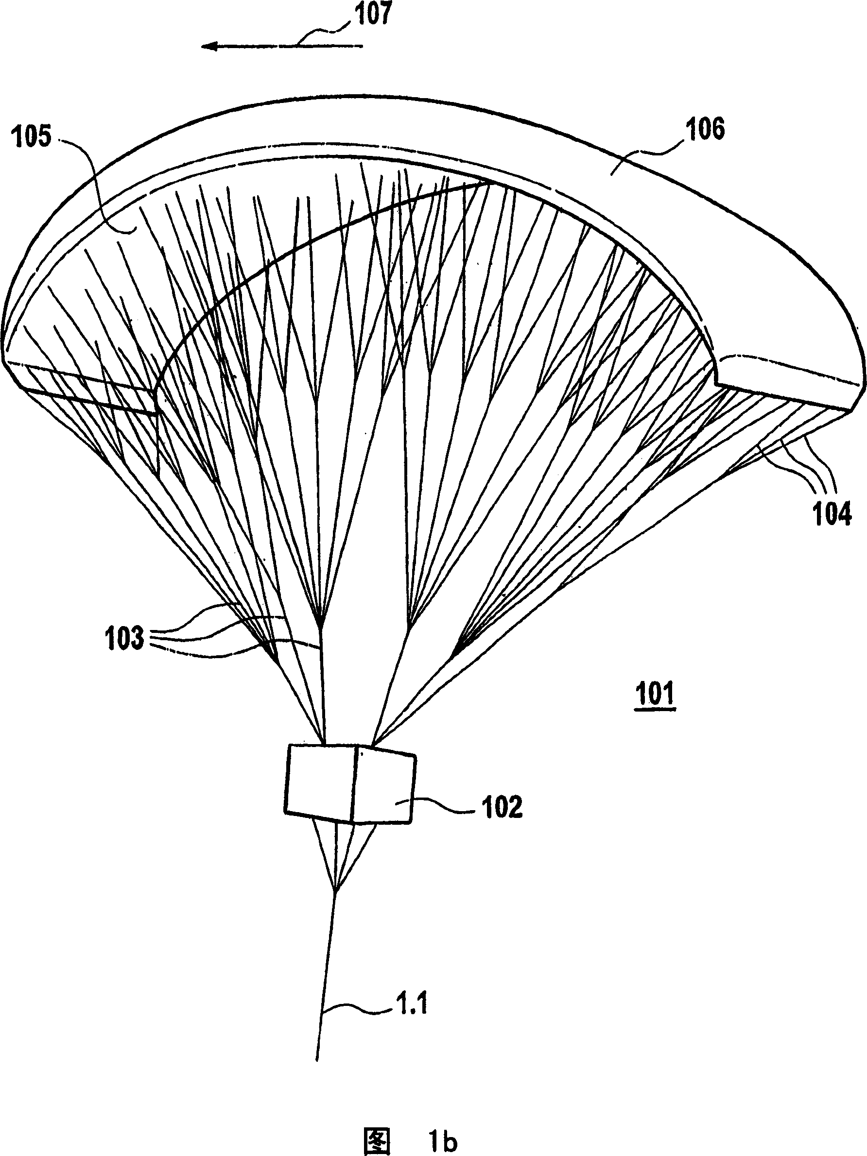
[0041] FIG. 1 depicts a vessel towed by a kite-sail system according to the invention in an oblique view. In this case a windward element 1 is connected to a ship 4 via a force application device 2 situated at the bow of the ship via traction cables 1 . 1 . The traction ropes 1.1 lead to a central gondola 1.2, from which a plurality of fixed ropes 1.3 lead, which lead to the windward element 1 formed in the form of a kite sail in the manner of a paraglider and give the necessary shape in the kite . For details, refer to the description below. The schematic wind direction on the windward element 1 is denoted by W. The corresponding wind vector is represented by its magnitude and direction. Its variation over time is optionally also represented by a parameter B representing the gust, which forms the time-average difference of the wind speed from the mean value and is represented as a scalar, which approximately forms the radius of a sphere around the tip of the wind vector W....


PUM


Abstract

Disclosed is a placement system for a free-flying kite-type wind-attacked element (101) in a watercraft in which the kite-type wind-attacked element (101) comprising a profiled wing is connected to the vessel body via a traction rope (1.1). Said wind-attacked element (101) can be guided from a neutral position on board the watercraft into a raised position that is free from obstacles located at the same or a higher level. An azimuthally pivotable fixture (181) is provided by means of which the wind-attacked element (101) can be brought into a position in which the same is exposed to an sufficient wind effect. Furthermore, a docking receiving device (181) is provided which is to be removably connected to the docking adapter of the wind-attacked element (101) on the side facing away from the wind while also allowing the wind-attacked element to be furled with the aid of automatically engaging holding means.

Description

technical field [0001] The invention relates to a deployment system for a free-flying kite-type windward element in a ship with a wind drive. Background technique [0002] By literature: Ship Propulsive Kites, An Initial study by J.F.Wellicomeand S.Williams, University of Southampton, ISSN 0140 3818 SSSU19Kapitel 4.1.2 "Non Powered Drouge Launch" Known that this kite sail type windward component for free flying out Open the system. [0003] A disadvantage of such deployment systems, which are only outlined in the known literature and which do not fully deploy, is that the windward element must be deployed by means of an additional auxiliary drive in the form of a parachute. Furthermore, no measures are seen which would also allow the larger windward element to be protected more reliably. Contents of the invention [0004] The object of the present invention is to provide measures for such deployment systems which enable the windward system to be activated in a manner sui...

Claims


Application Information

Patent Timeline
Patent Type & Authority Applications(China)
IPC IPC(8): B63H9/06
CPCB63H9/0685B63H9/072B63H9/071B63H9/069B63B2035/009Y02T70/5236
Inventor S·瓦拉格J·博哈姆
Owner SKYSAILS GMBH & CO KG
Why Eureka
Try Eureka