Heat exchange type ventilator

A ventilation device and heat exchange element technology, applied in heating methods, household heating, heat recovery systems, etc., can solve the problems of increased resistance of air supply and exhaust passages, larger overall size of the device, and poor construction. Achieve the effects of eliminating redundant space, realizing miniaturization, and improving air supply performance

Inactive Publication Date: 2007-05-23
PANASONIC CORP
View PDF2 Cites 10 Cited by
  • Summary
  • Abstract
  • Description
  • Claims
  • Application Information

AI Technical Summary

Problems solved by technology

Therefore, it is necessary to open two through-holes on the structure such as the wall of the building, so there is a disadvantage that the workability is poor and the airtightness of the building is impaired.
[0008] Moreover, in the latter heat exchange type ventilator, the double-layer duct that connects the interior is divided into the exhaust air path and the air supply air path, even if it overcomes the shortcomings of the construction and the airtightness of the building, because the double The exhaust air path and air supply air path of the layer duct must be connected with the exhaust air blower and air supply air blower respectively, so that the overall size of the device will also increase
In addition, the resistance of the air supply passage and the exhaust passage increases, and there is still a disadvantage that the ventilation performance of simultaneous supply and exhaust cannot be sufficiently obtained.

Method used


Image

  • Heat exchange type ventilator
  • Heat exchange type ventilator
  • Heat exchange type ventilator

Examples


Embodiment Construction

[0041] The heat exchange type ventilator of the present invention is accommodated and installed on the inner side of the top surface, for example.

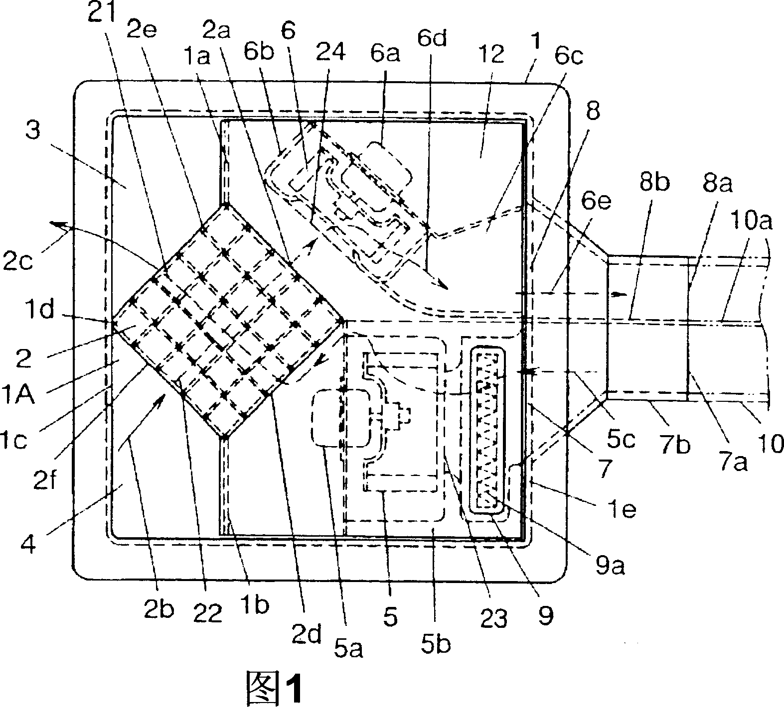
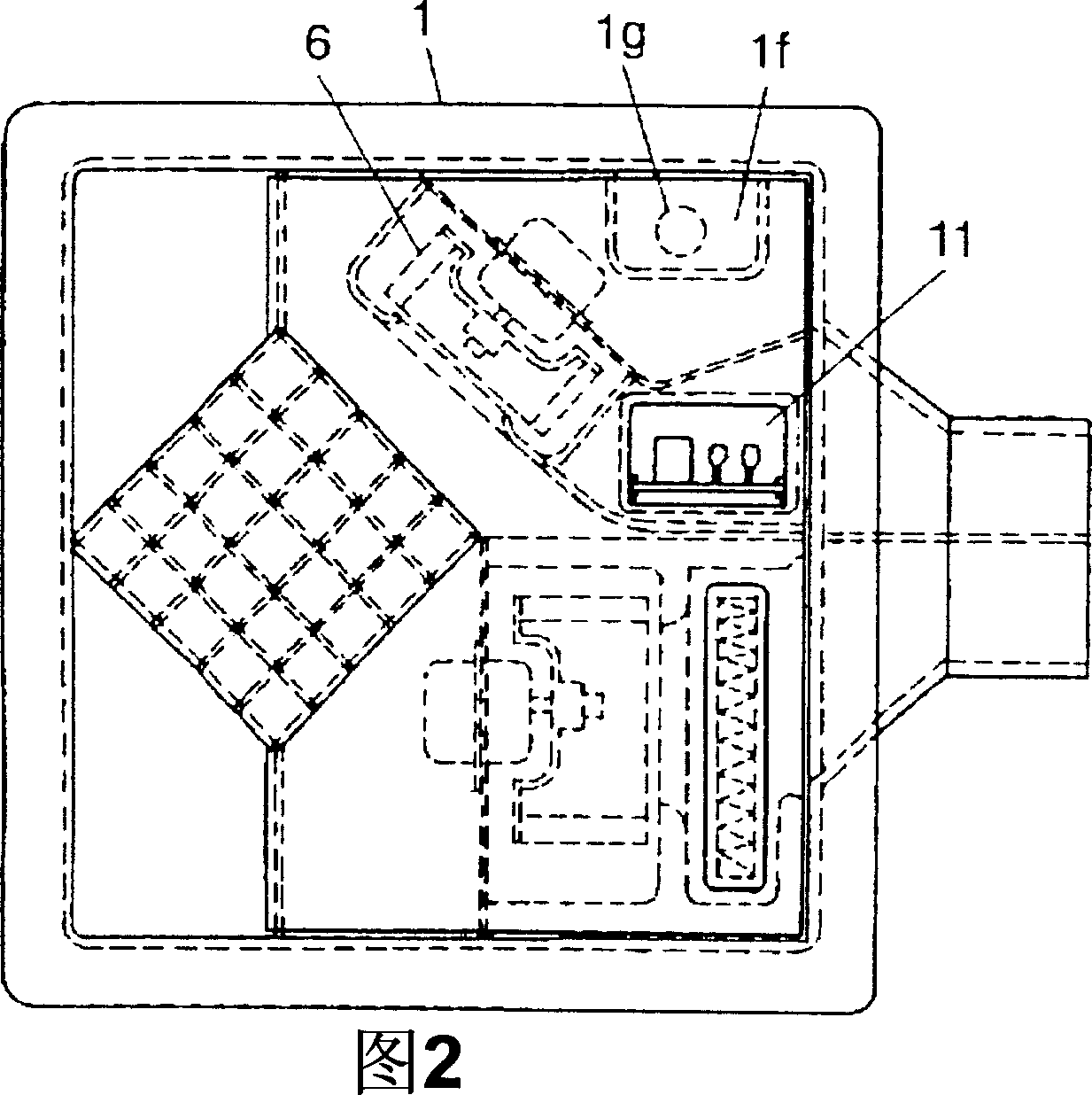
[0042] Fig. 1 is a view showing the structure of the heat exchange type ventilator according to the present invention, viewed from the opening side of the case. As shown in FIG. 1 , the heat exchange type ventilator of the present invention includes a box body having an opening 1A on the lower surface thereof and having a quadrangular cross-section. A plurality of exhaust flow paths 22 and supply flow paths 21 are alternately laminated in the depth direction of the housing 1 through the heat exchange plate so that the exhaust flow paths 22 and the supply flow paths 21 intersect each other. It has a heat exchange element 2 that performs heat exchange between the supply air flow and the exhaust air flow, and reduces energy loss through ventilation. It has the air supply blower 5 formed by the air supply blower motor 5a and the air ...


PUM


Abstract

A heat exchange type ventilator enabling a reduction in the size of a device body, comprising a box (1) installed on the surface of a ceiling, having an opening part (1A) in the lower surface thereof, and having a cross section of square shape. A large number of exhaust flow passages (22) and intake flow passages (21) are alternately stacked on each other in the depth direction of the box body (1) so that the exhaust flow passages (22) and the intake flow passages (21) are allowed to cross each other through heat exchange boards. The box also comprises a heat exchange element (2) exchanging heat between an intake flow and an exhaust flow and an intake blower (5) communicating with the intake flow inflow surface (2d) of the heat exchange element (2). The box further comprises an exhaust blower (6) communicating with the exhaust flow outflow surface (2a) of the heat exchange element (2) and an outdoor side intake flow passage inlet (7) formed in the side face of the box on the opposite side of an indoor side intake flow passage outlet (3) on the upstream side of the intake blower (5). In addition, the box comprises, on the downstream side of the exhaust blower (6), an indoor side exhaust flow passage inlet (4) and an outdoor side exhaust flow passage outlet (8) formed in the side face of the box on the opposite side of the indoor side exhaust flow passage inlet, and the outdoor side intake flow passage inlet (7) and the outdoor side exhaust flow passage outlet (8) are positioned adjacent to each other and allowed to communicate with the inside of a bimetallic tube (10) formed by dividing the inside of the tube into two flow passages.

Description

technical field [0001] The present invention relates to a heat exchange type ventilator for exchanging heat between indoor air and outdoor air through a double-layer duct internally divided into an exhaust flow path and an air supply path. Background technique [0002] In the prior art, as such a heat exchange type ventilator, there is known a heat exchange type ventilator that has a heat exchange element inside, performs heat exchange between indoor air and outdoor air, and reduces the energy loss of the indoor environment through ventilation. gas device (for example, Japanese Patent Application Publication No. 57-46732, with reference to Fig. 1). [0003] Such a heat exchange type ventilator divides the inside of a box-shaped main body attached to a building into an exhaust passage and an air supply passage. A blower for air supply and exhaust is provided inside the exhaust passage and the air supply passage, the rotation axis of which is horizontal to the top surface. T...

Claims


Application Information

Patent Timeline
Patent Type & Authority Applications(China)
IPC IPC(8): F24F7/08
CPCY02B30/563F24F12/006Y02B30/16F24F2221/14Y02B30/56F24F7/08
Inventor 南里信幸松本隆善五十里良雄下地健一中岛列树
Owner PANASONIC CORP
Why Eureka
Try Eureka