fuel cell system

A fuel cell system and fuel system technology, applied in the direction of fuel cells, circuits, electrical components, etc., can solve the problems of high cost, low catalytic efficiency, and low utilization rate of fuel cell systems, and achieve improved drainage and exhaust performance, faster The effect of high gas flow rate and high utilization rate

Active Publication Date: 2020-06-09
顺风恒劲氢能源发展(上海)有限公司
View PDF5 Cites 0 Cited by
  • Summary
  • Abstract
  • Description
  • Claims
  • Application Information

AI Technical Summary

Problems solved by technology

The above deflector can play the functions of humidification, heat dissipation, and drainage. However, there is a gap between the deflector and the diffusion layer, and the reaction gas reacts on the surface of the diffusion layer and the catalytic layer. The utilization rate is not high, and the catalytic efficiency is low. This in turn leads to high operating costs of the fuel cell system

Method used


Image

  • fuel cell system
  • fuel cell system
  • fuel cell system

Examples


Embodiment 1

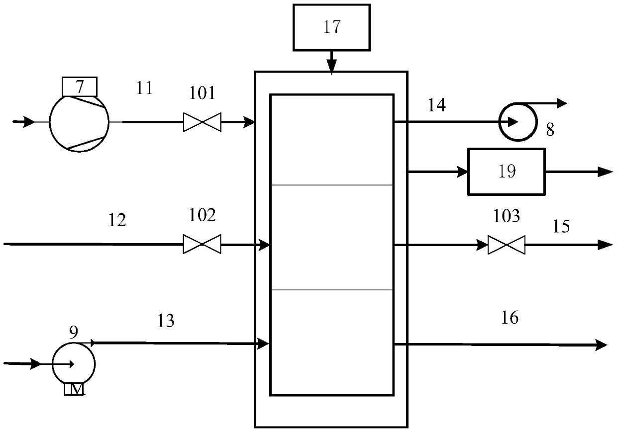
[0041] A fuel cell system such as figure 1 and figure 2 As shown, it includes a fuel cell stack, and a fuel system 12, an oxidant system 11, a cooling system 13 and an exhaust system that are all connected to the fuel cell stack. The above-mentioned oxidant system 11 is connected to the oxidant of the fuel cell stack by an air compressor 7 Inlet 42, and valve 101 is arranged on this pipeline, and the oxidant outlet 43 of fuel cell stack connects oxidant outlet pipeline 14; Fuel system 12 is connected to the fuel inlet 44 of fuel cell stack by fuel storage tank through pipeline, and on this pipeline A valve 102 is provided, and the fuel outlet 45 of the fuel cell stack is connected to the fuel outlet pipeline 15, and the fuel outlet pipeline 15 is provided with a valve 103; the above-mentioned cooling system 13 is connected to the cooling fluid of the fuel cell stack by the cooling fluid compressor 9 through a pipeline. The inlet 46, the cooling fluid outlet 47 of the fuel ce...

Embodiment 2

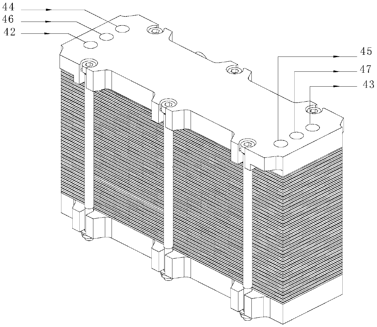
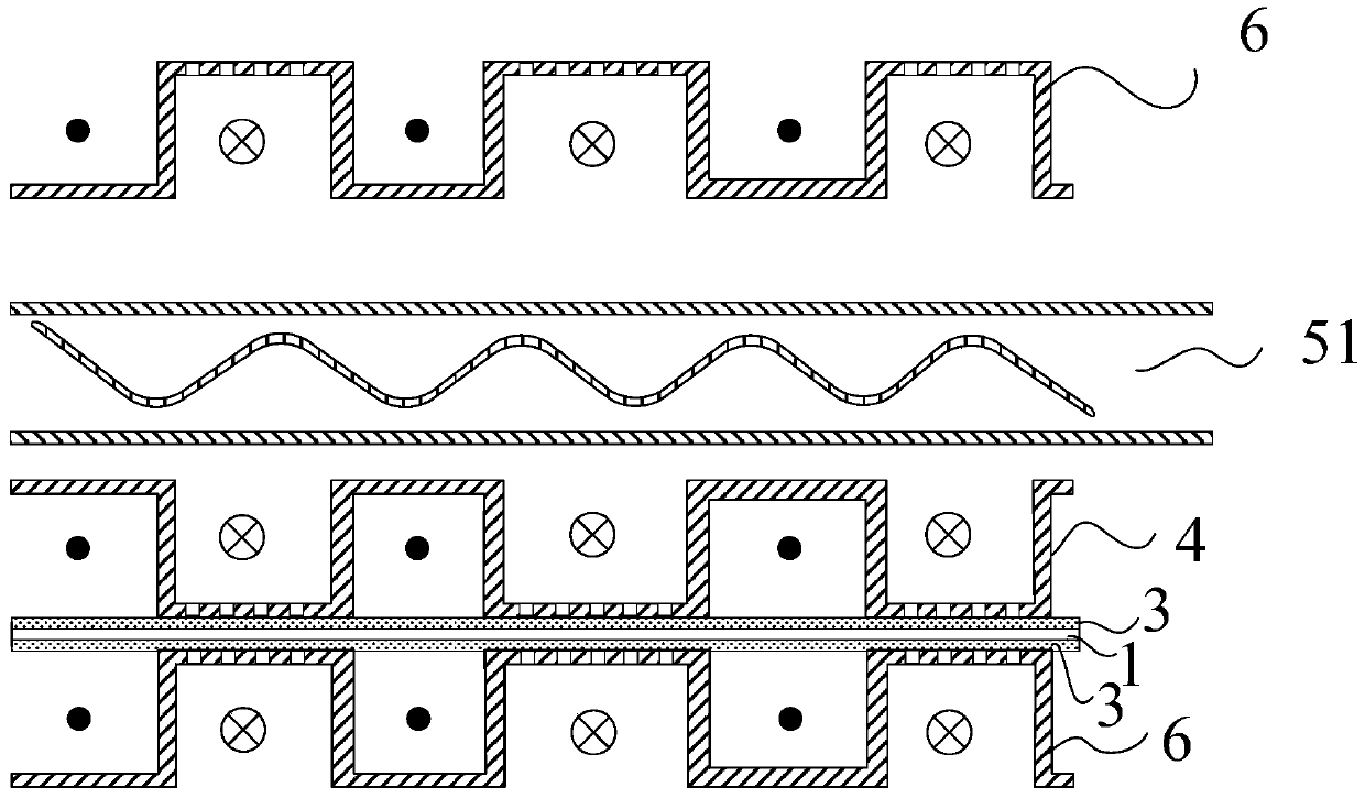
[0051] This embodiment proposes a fuel cell system, the structure of the fuel cell stack in the fuel cell system is as follows Figure 8 As shown, the fuel cell stack has an oxidant inlet 42, an oxidant outlet 43, a fuel inlet 44 and a fuel outlet 45, and the MEA and the cathode plate 4 and the anode plate 6 in the single cell are clamped as Figure 7 As shown, the single cell is composed of a cathode plate 4 and an anode plate 6 sandwiching an MEA, and the MEA includes a proton exchange membrane 1 and catalytic layers 2 arranged on both sides of the proton exchange membrane 1 (such as Figure 4 shown) and the fluid transport layer 3 arranged outside the catalytic layer 2, wherein the cathode plate 4 and the anode plate 6 are arranged between the separator 5, the separator 5 is an air-tight plate, preferably a solid plate, the cathode plate 4 and the anode One side of each plate 6 is provided with a fluid inlet passage for the inlet end, and the other side is provided with a f...

Embodiment 3

[0053] The similarities between this embodiment and Embodiment 1 will not be described, and only the differences will be described.

[0054] The significant difference between this embodiment and Embodiment 1 is that the fuel cell system in this embodiment does not include an air extraction device, and the oxidant system 11 is provided by an air compressor 7 (such as figure 1 shown) is connected to the oxidant inlet of the fuel cell stack through pipelines to form a positive pressure on the inlet side of the cathode plate 4 (relative to an atmospheric pressure, that is, greater than 1 atmospheric pressure), and form a pressure difference with the outlet side of the cathode plate 4. In principle, the fuel system 12 is connected to the fuel inlet 44 of the fuel cell stack by the fuel storage tank through a pipeline to form a positive pressure on the inlet side of the anode plate 6 (relative to an atmospheric pressure, that is, greater than 1 atmospheric pressure), and the anode p...


PUM


Abstract

The invention discloses a fuel cell system. The fuel cell system comprises a fuel cell pile, and a fuel system, an oxidizing agent system, a cooling system and a discharging system which are all connected with the fuel cell pile, wherein the fuel cell pile is formed by pressing and fixing multiple laminated single cells through pressing plates; each single cell is formed by sandwiching an MEA by a negative electrode plate and a positive electrode plate; through holes for allowing fluid to pass through are formed in the positive electrode plate and the negative electrode plate, and the MEA is arranged tightly close to the through holes in the positive electrode plate and the negative electrode plate; and the discharging system is connected with an air exhausting system. Compared with the prior art, a fluid incoming channel is formed in one surface of each of the positive electrode plate and the negative electrode plate while a fluid discharging channel is formed in the other surface; the channels in the two sides of the electrode plates are connected through the multiple micro through holes in the electrode plates; a reaction fluid arrives at the MEA interface to be reacted, and the unreacted part and the generated fluid enter the fluid discharging channels from the through holes and then flow out of the outlets; therefore, the fluid is in contact with a catalyst layer at a higher ratio and the reaction efficiency is improved; and meanwhile, extremely excellent water discharging performance and low requirement on a fluid transport layer are achieved.

Description

technical field [0001] The invention relates to the field of fuel cells, in particular to a fuel cell system. Background technique [0002] Fuel cells, especially hydrogen fuel cells, are clean energy sources that are environmentally friendly. As a high-efficiency and environmentally friendly power generation device, fuel cells have become a hot spot in research and development in various countries in recent years. The important component contained in it is the diffusion layer. The diffusion layer is composed of conductive porous materials, which play a role in supporting the catalytic layer, collecting current, and conducting gas. It realizes the redistribution of reaction gas and product water between the flow field and the catalytic layer, and is one of the key components affecting the performance of the electrode. However, in the existing fuel cell system, the deflector and the diffusion layer cannot cooperate well. [0003] For example, Chinese patent CN 204720508 U d...

Claims


Application Information

Patent Timeline
Patent Type & Authority Patents(China)
IPC IPC(8): H01M8/0258H01M8/04119H01M8/04029
CPCH01M8/0258H01M8/04029H01M8/04126H01M8/04156Y02E60/50
Inventor 高勇
Owner 顺风恒劲氢能源发展(上海)有限公司
Why Eureka
Try Eureka