
Hydraulic sub-station

A hydraulic substation and hydraulic technology, which is applied to equipment loaded into pressure vessels, gas/liquid distribution and storage, ship construction details, etc., can solve problems such as damage, shortened life of hydraulic pumps and hydraulic valves, and high power consumption

Pending Publication Date: 2018-07-27
TIANJIN LIANGHUA NEW ENERGY TECH
View PDF15 Cites 0 Cited by
  • Summary
  • Abstract
  • Description
  • Claims
  • Application Information

AI Technical Summary

Problems solved by technology

The sub-station pressurization system consists of double pumps with equal displacement. The displacement of each hydraulic pump is 1500Nm3 / h. When the gas filling load of the gas filling station is low, the hydraulic pump starts and stops frequently, and the power consumption is too high; Due to the limitations of the hydraulic natural gas vehicle refueling substation system, a single hydraulic pump cannot operate. Regardless of whether the refueling load of the gas station is high or low, the two hydraulic pumps will start and stop sequentially after the PLC control system runs. Start and stop very frequently, resulting in a lot of power waste and low work efficiency
During the operation of the two hydraulic pumps, air bubbles will be generated in the oil suction pipeline, which will cause vibration and noise in the slightest, and cavitation in severe cases, causing damage to the hydraulic pumps and hydraulic valves, which shortens the life of the hydraulic pumps and hydraulic valves and reduces the hydraulic pressure. Substation exhaust volume

Method used


Image

  • Hydraulic sub-station

Examples


Embodiment Construction

[0061] It should be noted that, in the case of no conflict, the embodiments of the present invention and the features in the embodiments can be combined with each other.

[0062] In describing the present invention, it should be understood that the terms "center", "longitudinal", "transverse", "upper", "lower", "front", "rear", "left", "right", " The orientations or positional relationships indicated by "vertical", "horizontal", "top", "bottom", "inner" and "outer" are based on the orientations or positional relationships shown in the drawings, and are only for the convenience of describing the present invention and Simplified descriptions, rather than indicating or implying that the device or element referred to must have a particular orientation, be constructed and operate in a particular orientation, and thus should not be construed as limiting the invention. In addition, the terms "first", "second", etc. are used for descriptive purposes only, and should not be understood ...


PUM


Abstract

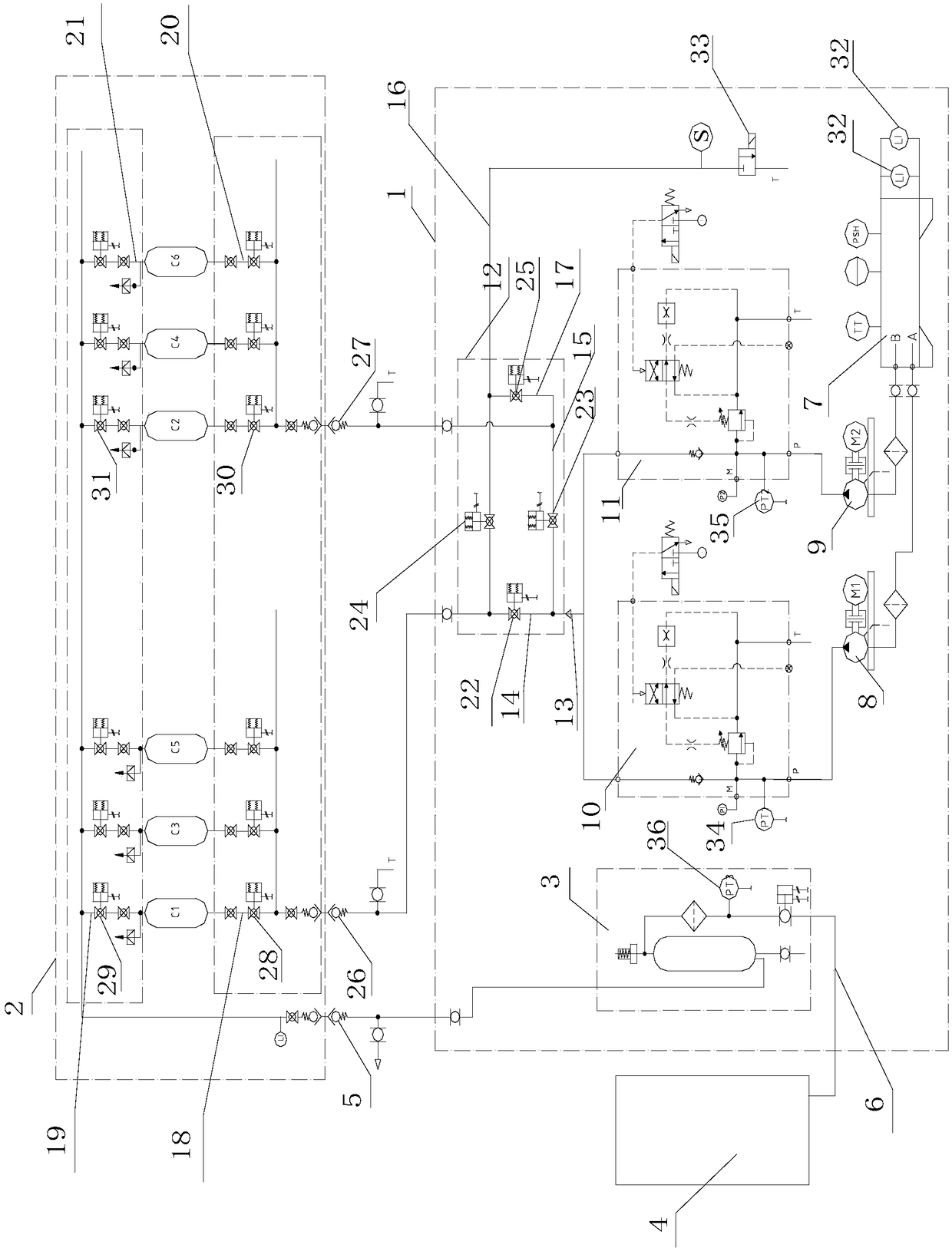
The invention provides a hydraulic sub-station. The hydraulic sub-station comprises a hydraulic sub-station skid body, a hydraulic sub-station trailer, a natural gas buffer bottle and a gas-filling machine. The hydraulic sub-station skid body and the hydraulic sub-station trailer are connected through a hydraulic high-pressure hose, the hydraulic sub-station trailer is connected with the natural gas buffer bottle through a natural gas high-pressure hose, the natural gas buffer bottle and the gas-filling machine are connected through an outlet pipeline, and the hydraulic sub-station controls opening of a valve through a PLC automatic control system. The hydraulic sub-station skid body comprises a hydraulic oil tank, a first hydraulic pump, a second hydraulic pump, a first valve block, a second valve block and a reversing valve set. The hydraulic sub-station trailer comprises a plurality of steel bottles divided into two sets. The two hydraulic pumps can operate separately and can also operate simultaneously, thus the situation that the two hydraulic pumps are started frequently when the gas-filling load of a gas-filling station is changed is avoided, power consumption is reduced bya large margin, the gas-filling speed of the sub-station is increased, and the working efficiency is improved.

Description

technical field [0001] The invention belongs to the technical field of natural gas filling devices, in particular to a hydraulic substation. Background technique [0002] Hydraulic natural gas vehicle refueling substations have been widely used nationwide due to their advantages of less equipment, small footprint, short construction period and trailer unloading rate as high as 95%-97%. [0003] With the increase in the number of natural gas vehicle refueling sub-stations, the competition among refueling stations is intensifying. In order to shorten the refueling time of vehicles and reduce the waiting time for refueling, especially to meet the refueling needs of large-capacity natural gas vehicles such as buses and intercity buses, the technology of large-displacement hydraulic natural gas vehicle refueling substations has emerged as the times require. [0004] Displacement 3000Nm 3 The dual-pump hydraulic natural gas vehicle refueling substation system per hour has become...

Claims


Application Information

Patent Timeline
IPC IPC(8): F17C5/06F17C13/00F17C13/02F17C13/04
CPCF17C5/06F17C13/002F17C13/02F17C13/025F17C13/04F17C2250/043F17C2270/0184F17C2221/033F17C2223/0123F17C2227/0192F17C2227/04F17C2250/032F17C2205/0323
Inventor 史志强
Owner TIANJIN LIANGHUA NEW ENERGY TECH
Learn More