Marine pipe laying system method and hoisting device

A pipeline laying and submarine pipeline technology, which is applied in pipeline laying and maintenance, cranes, mechanical equipment, etc., can solve the problems of slow upward movement of moving blocks and limit the length of pipeline laying, and achieve the effect of saving time and reducing costs

Active Publication Date: 2007-06-06
ITREC BV
View PDF1 Cites 6 Cited by
  • Summary
  • Abstract
  • Description
  • Claims
  • Application Information

AI Technical Summary

Problems solved by technology

[0011] When laying the pipeline, a hoisting system with enough sheaves must be used to support the load of the pipeline, but its disadvantage is that whe

Method used


Image

  • Marine pipe laying system method and hoisting device
  • Marine pipe laying system method and hoisting device
  • Marine pipe laying system method and hoisting device

Examples


Embodiment Construction

[0062]The system involves a vertical or near-vertical pipelaying technique, such as the J-lay technique, for introducing a pipe from a ship into the water in a substantially vertical orientation. The system provides an improved pipeline laying system for vertical or near vertical marine pipeline laying, especially deep water pipeline laying.

[0063] The method described with reference to Figures 1-7 relates to an efficient method for laying subsea pipelines vertically or near vertically.

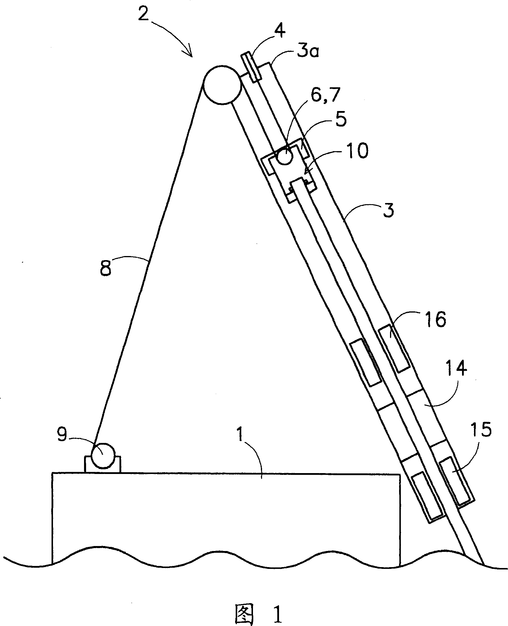
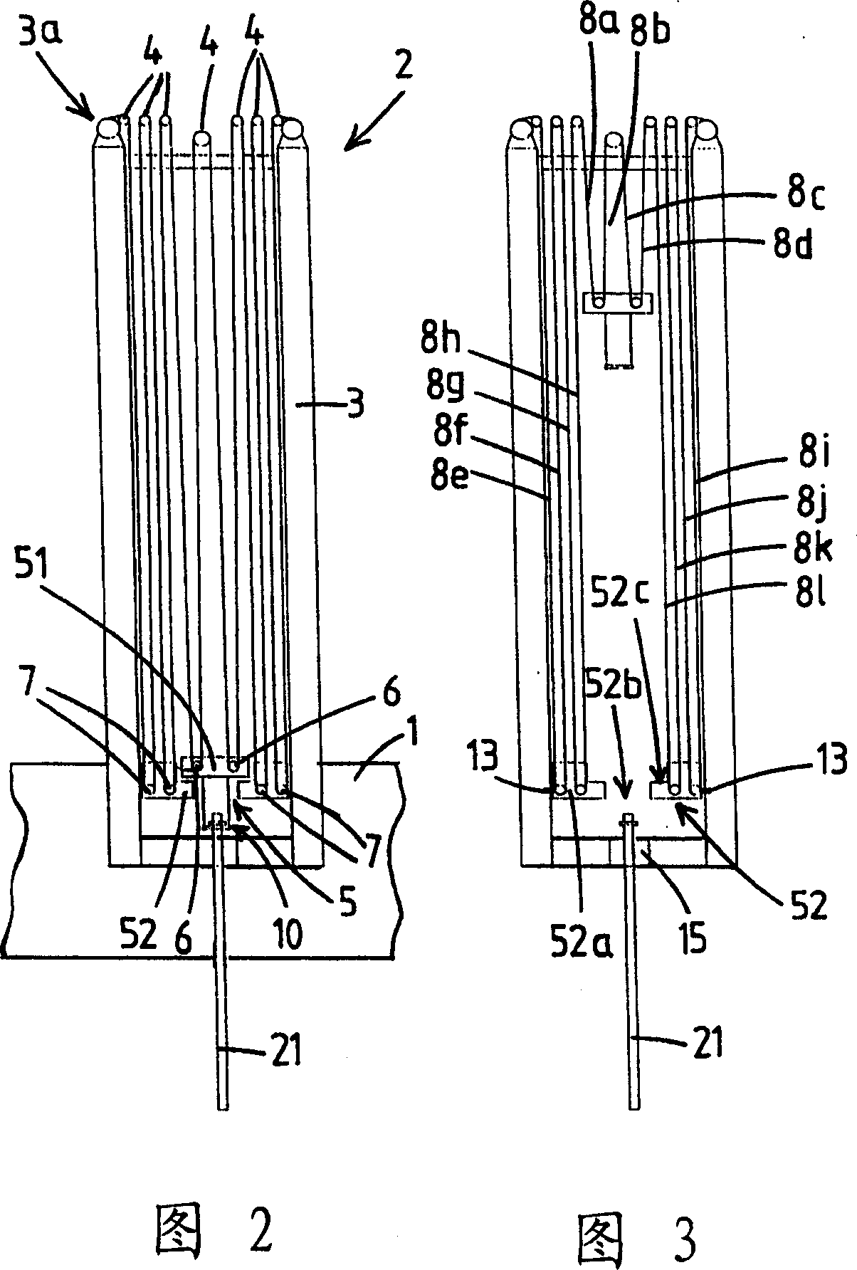
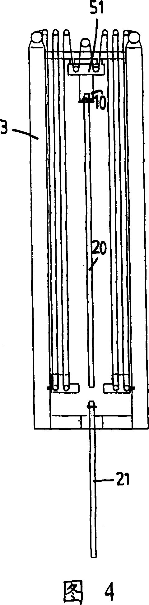
[0064] The pipelaying system provides the vessel as the main support structure. A part of the ship is shown with reference number 1 in FIGS. 1 and 2 . In Figures 3-7, the boat 1 is omitted for clarity of the drawings.

[0065] Lifting equipment 2 is provided on the ship 1 . The lifting device 2 comprises a tower 3 with a tower top surface 3a. A cable pulley 4 is provided on the top surface 3a of the tower.

[0066] The lifting device 2 also includes a moving mass 5 movably connected to...


PUM


Abstract

The invention relates to marine pipe laying. For laying of an offshore pipeline, a system is used having a hoisting device. The hoisting device comprises a tower with a tower top side provided with cable pulleys. Furthermore the hoisting device has a traveling block which is displaceably attached to the tower. The traveling block comprises a first block and a second block, both provided with cable pulleys. The first block is provided with a clamp for holding a pipe section to be connected to the pipeline as well as for lowering the pipeline after the pipe section is connected to the pipeline. The hoisting device has a hoisting cable and a winch , the hoisting cable being guided over the cable pulleys on both the tower top side and the traveling block. The traveling block is moveable with respect to the tower by operation of the hoisting winch. The first block and the second block are adapted to be releasably coupled, in which coupled state they can travel along the tower as a unit and are able to support the weight of the pipeline. The second block can be locked to the tower, such that the first block can travel along the tower while the second block remains stationary with respect to the tower.

Description

technical field [0001] The invention relates to an ocean pipeline laying system for laying a submarine pipeline, the system comprising: [0002] a) main support structure; [0003] b) the pipe connection station where the pipe section is connected to the uppermost end of the previous inlet pipe; [0004] c) a fixing clip for releasably fastening the uppermost end of the previous water inlet pipe, wherein the fixing clip is suitable for supporting the load of the previous water inlet pipe; [0005] d) Lifting equipment, said lifting equipment comprising: [0006] - a tower with a tower top face provided with cable pulleys, [0007] - a mobile block movably connected to the tower, provided with a cable pulley and a mobile clamp for clamping the pipe section to be connected to the pipe and lowering the pipe after the pipe section is connected to the pipe , [0008] - hoisting gear, comprising hoisting cables and winches, said hoisting cables being guided on sheaves above bot...

Claims


Application Information

Patent Timeline
IPC IPC(8): F16L1/12B66C23/52
CPCB66D3/043F16L1/207
Inventor J·鲁登伯格T·W·A·维梅杰L·A·M·C·范登阿素姆
Owner ITREC BV
Why Eureka
Try Eureka