
Inspection machine

A technology for a detector and a detection container, which is applied in the field of detectors, can solve problems such as time-consuming and labor-intensive modification work, and achieve the effect of simplifying the structure cost and reliable cost.

Inactive Publication Date: 2007-06-06
KRONES AG
View PDF4 Cites 0 Cited by
  • Summary
  • Abstract
  • Description
  • Claims
  • Application Information

AI Technical Summary

Problems solved by technology

Time-consuming and labor-intensive conversion work when switching to other bottle sizes

Method used


Image

  • Inspection machine
  • Inspection machine

Examples


Embodiment Construction

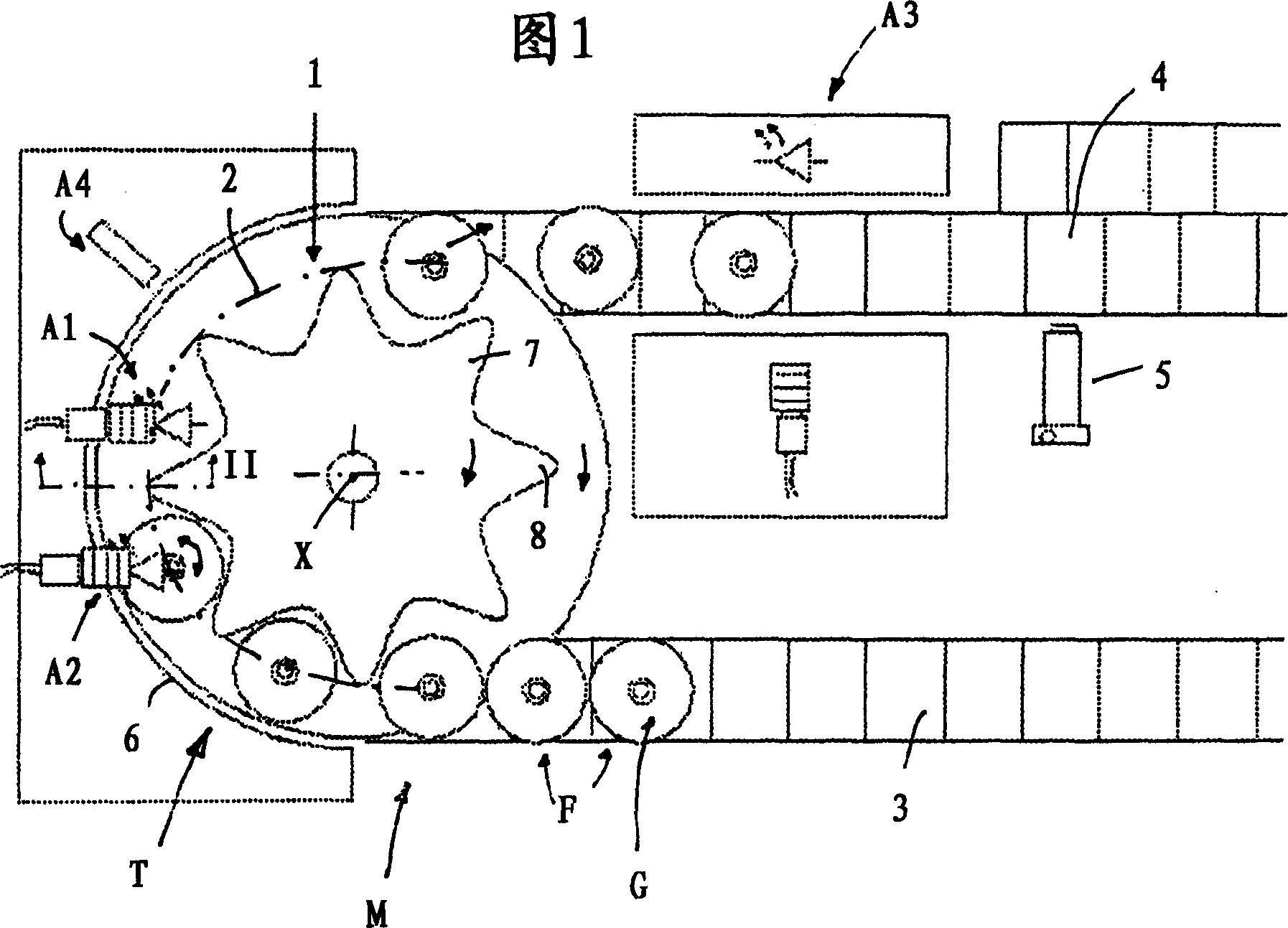
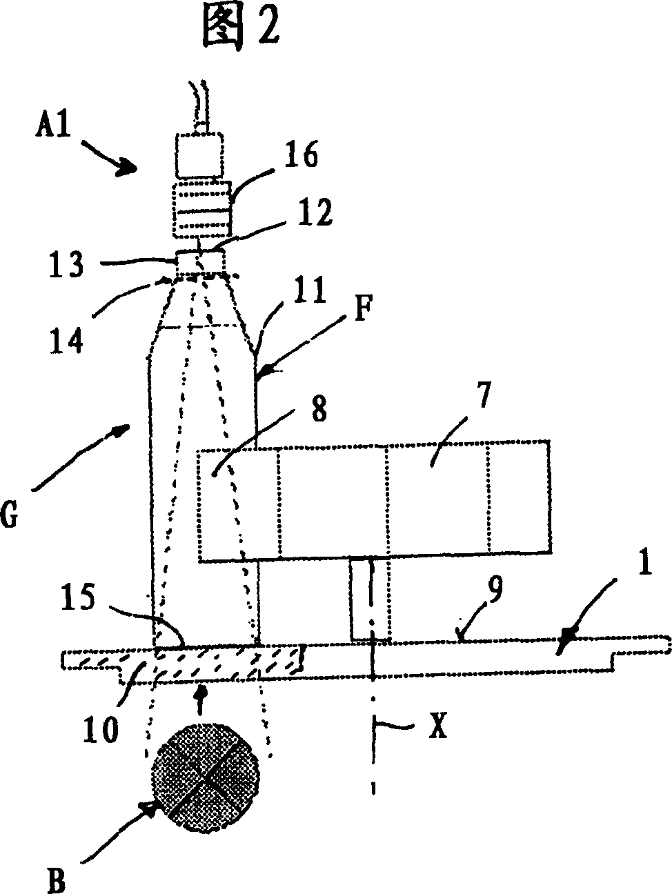
[0027] A detector M, shown in schematic top view in FIG. 1 , is used to inspect containers G, in particular bottles F, for example made of glass or plastic (PET), for damage and / or soiling. The detector comprises a transport device T by means of which the containers G are transported and detected continuously or intermittently on a semicircle spanning approximately 180°. In a simple embodiment of the detector M (not shown), the transport means T consists only of a substantially circular disc 1 drivable in rotation about the axis X, on the upper surface 9 of the disc ( FIG. 2 ). Containers G spaced apart from one another are transported vertically along an arcuate path 2 next to at least one inspection device A1 , A2 , A4 placed above the disc and inspected. The discs 1 carry the containers and are spaced from each other by gravity and friction. The containers are delivered by means of an input device 3, for example one after the other, onto the disc 1, and from the disc throu...


PUM


Abstract

An inspection machine (M) for checking particularly bottles (F) comprises a conveyor (T) for transporting the bottles along an arched path ( 2 ) and past at least one inspection device (A 1 -A 4 ) associated with the arched path, and at least one illumination device ( 3 ) which is arranged below the arched path and shines light through the bottles from below and upward. The conveyor (T) presents a disk which can be driven in rotation, and whose top side ( 9 ) presents a standing surface for the bottom ( 15 ) of each bottle to be transported, which stands directly on the surface, where the disk is constructed so that it is transparent at least in some area.

Description

technical field [0001] The invention relates to a detector of the type stated in the preamble of patent claim 1 . Background technique [0002] The detector known from EP 0 894 544 A has a star gear as the transmission device, which is equipped with clamping clips on the peripheral surface. Each gripper grips the container at approximately half-height on both sides, and conveys the container along an arcuate path past an inspection device. The clips transport the container bottom off the ground. For the bottom inspection device following the curved path, a stationary protective disk or diffuser disk is arranged at a distance below the ground-free container bottom, which is illuminated from below by an illumination device. The mechanical complexity for the gripping and lift-off transport of the containers, especially the bottles, is very high due to the detectors. Furthermore, the clips must also be adapted, if necessary, for other bottle sizes. A control device for the c...

Claims


Application Information

Patent Timeline
Patent Type & Authority Applications(China)
IPC IPC(8): G01N21/90G01N35/02G01N35/04
CPCG01N21/90
Inventor 彼得·林德纳瓦尔特·珀佩尔
Owner KRONES AG
Learn More