
Plasma displaying device and driving method thereof

A technology of a display device and a driving method, which is applied in the directions of identification devices, static indicators, instruments, etc., can solve the problems of unstable addressing discharge and the like

Inactive Publication Date: 2007-06-06
LG ELECTRONICS(NANJING) PLASMA CO LTD
View PDF0 Cites 2 Cited by
  • Summary
  • Abstract
  • Description
  • Claims
  • Application Information

AI Technical Summary

Problems solved by technology

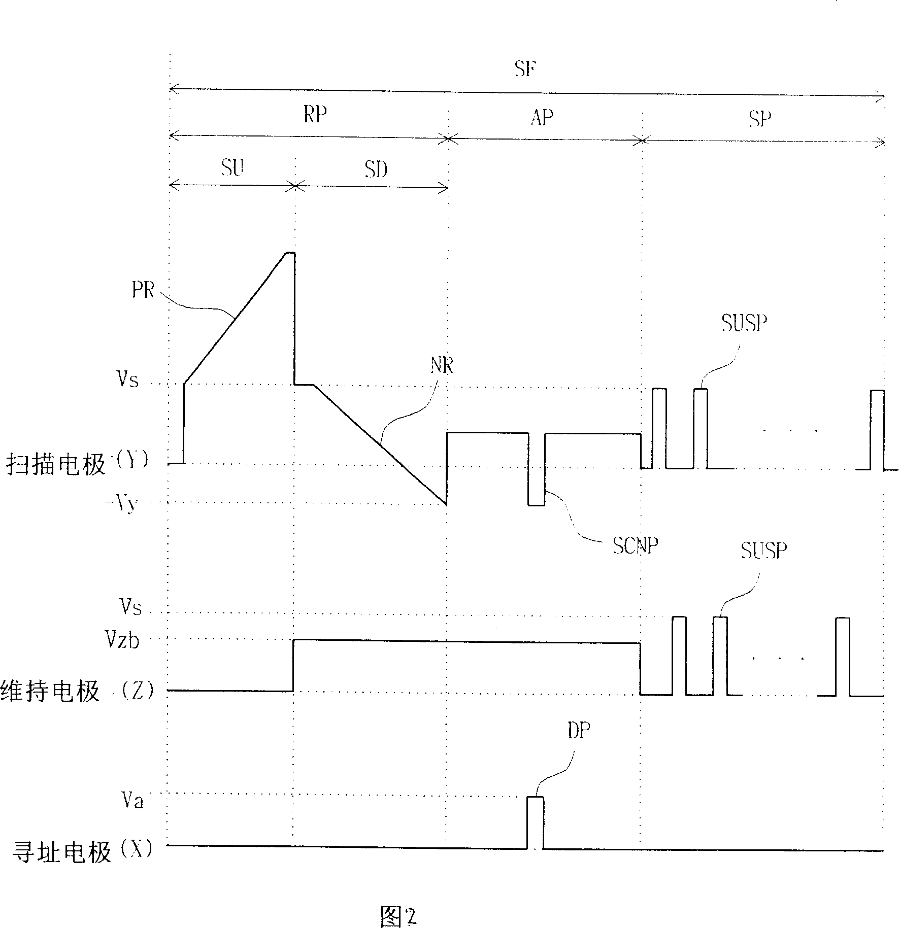
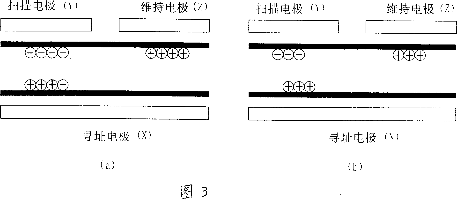
[0015] At the same time, contrary to the initial pulses input at the same time, the scan pulses are input sequentially, because of this characteristic, the addressing discharge becomes less stable as the wall charges are lost closer to the second half of the scan

Method used


Image

  • Plasma displaying device and driving method thereof
  • Plasma displaying device and driving method thereof
  • Plasma displaying device and driving method thereof

Examples


Embodiment Construction

[0047] Embodiments of the plasma display device and its driving method in the present invention will be described in detail below with reference to the accompanying drawings.

[0048] FIG. 4 is a schematic diagram of a plasma display device in the first embodiment of the present invention.

[0049] As shown in FIG. 4, the plasma display device in the first embodiment of the present invention includes the following parts: in the initial period, the address period and the sustain period, according to the address electrodes (X1 to Xm), scan electrodes (Y1 to Yn) And the scanning sequence is divided into upper and lower sustain electrode groups (ZT, ZB), and a certain driving pulse is input to the sustain electrode (Z) connected to the electrode group to generate a gas discharge in the discharge space and display a plasma panel (400) ; The data driver (42) that provides input to the address electrodes (X1 to Xm) formed on the rear panel (not shown); the scan driver (43) that drive...


PUM


Abstract

The invention involves plasma display device and its driving method. The plasma display device includes following parts: panels maintaining multiple electrodes which are divided into upper part and lower part maintaining electrode clusters according to their scanning order and have same connections in the same electrode cluster; drivers to drive electrodes; descending control part which will reduce the electronic reduction between scanning electrodes and lower part maintaining electrode cluster when descendent waveform is entered to scanning electrodes. Driving method is the plasma display devices driving method, including reducing the electronic reduction between maintaining electrode clusters and scanning electrodes in the period that descendent waveform is entered.

Description

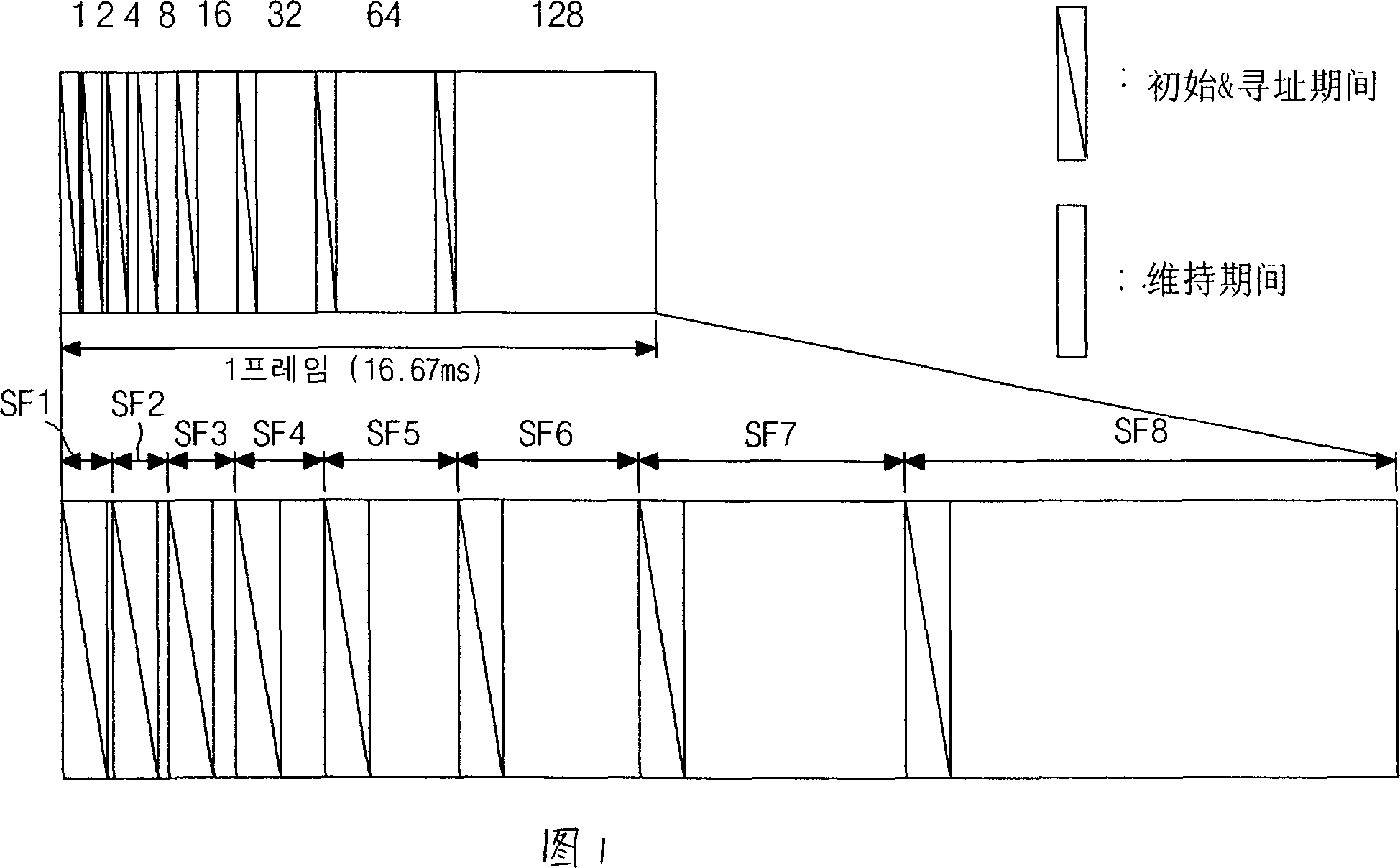
technical field [0001] The present invention relates to a plasma display device and a driving method thereof, and more specifically, it relates to a plasma display device and a driving method thereof which improve contrast characteristics and drive locking and save manufacturing costs. Background technique [0002] A plasma display panel (Plasma Display Panel; hereinafter referred to as "PDP") utilizes ultraviolet rays generated during discharge of inert gas mixtures such as He+Xe, Ne+Xe, He+Xe+Ne, etc. to make phosphors emit light and display images. Such a PDP can be made thinner and larger, and its image quality has been continuously improved with recent technological developments. [0003] FIG. 1 is a schematic diagram of a gray-scale picture of an 8-byte default code for displaying a 256-level gray-scale picture on a PDP. [0004] Referring to Figure 1, in order to realize the gray-scale picture of the screen, a PDP divides a frame into multi...

Claims


Application Information

Patent Timeline
Patent Type & Authority Applications(China)
IPC IPC(8): G09F9/313H01J17/49G09G3/28G09G3/288
Inventor 崔正必
Owner LG ELECTRONICS(NANJING) PLASMA CO LTD
Learn More