Shaft cool electric machine

A technology of motor shaft and motor casing, applied in electrical components, electromechanical devices, electric components, etc., can solve the problems of unsatisfactory heat dissipation effect, affecting motor heat dissipation, and difficulty in dissipating motor heat.

Inactive Publication Date: 2007-06-06
池驰
View PDF0 Cites 10 Cited by
  • Summary
  • Abstract
  • Description
  • Claims
  • Application Information

AI Technical Summary

Problems solved by technology

The usual method is to use fan blades to dissipate heat. Although the purpose of heat dissipation is achieved, the effect of heat dissipation is not ideal. Generally, the heat of the motor is generated from the inside of the motor, and the sealing of the motor is also very important, because the sealing of the motor affects the performance of th

Method used


Image

  • Shaft cool electric machine
  • Shaft cool electric machine

Examples


Embodiment Construction

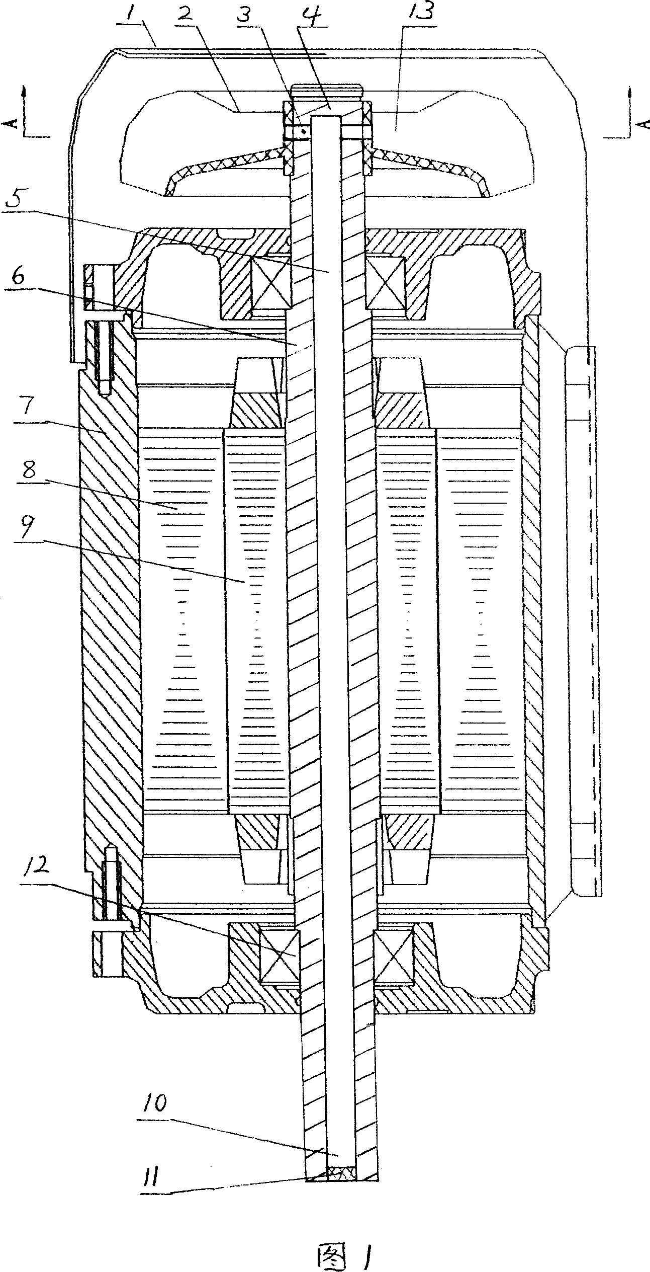
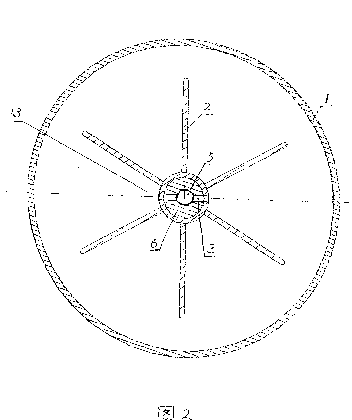
[0009] As shown in the figure, the shaft-cooled motor includes: a motor casing 7, a spindle 8, a rotor 9, a bearing 12, a fan blade 2, a hollow motor shaft 6, a wind cover 1, and a filter screen 11.

[0010] A hollow part 5 is provided inside the motor shaft to form a hollow motor shaft 6. The hollow part 5 at one end of the motor shaft 6 at one end of the fan blade 2 is sealed to become a sealed end 4, and the hollow part at the other end of the motor shaft 6 is a hollow end 10. The fixed place with the motor shaft 6 is provided with one or more through holes 3. In this embodiment, there are two through holes 3. The through holes 3 communicate with the hollow part 5 of the motor shaft 6 and the air guide space 13 of the fan blade 2. The air guide space 13 is located between the fan blades 2, the hollow part 5 is used to pass through the through hole 3 and the hollow end 10; the hollow end 10 of the motor shaft 6 is provided with a filter screen 11; the sealing end 4 of the mot...


PUM


Abstract

A motor of shaft cooling type is prepared as setting hollow portion at internal of motor shaft to form hollow motor shaft, sealing blade end of motor shaft to sealed end and setting another end of motor shaft to be hollow end, arranging one or multiple through hole at fixing position of blade and motor shaft, connecting said through hole to hollow portion of motor shaft and air guiding space of blade for making air at hollow portion of motor shaft flow continuously so as to achieve purpose of heat radiation.

Description

1. Technical field [0001] The invention relates to an electric machine. 2. Background technology [0002] The motors currently on the market need to be cooled because the high-speed rotation inside the motor will cause the motor to heat up during use. The usual method is to use fan blades to dissipate heat. Although the purpose of heat dissipation is achieved, the effect of heat dissipation is not ideal. Generally, the heat of the motor is generated from the inside of the motor, and the sealing of the motor is also very important, because the sealing of the motor affects the performance of the motor. Heat dissipation, so that the heat inside the motor is not easy to dissipate, so people have been looking for a method that can not only keep the seal of the motor but also solve the internal heating problem when the motor is working, so as to improve the working efficiency of the motor and prolong the service life of the motor bearing. . 3. Contents of the invention [0003...

Claims


Application Information

Patent Timeline
IPC IPC(8): H02K9/06H02K9/10
Inventor 池驰
Owner 池驰
Why Eureka
Try Eureka