Screw coupling for oil well pipe

A technology for threaded joints and pipes. It is used in threaded connections, pipes/pipe joints/pipes, drill pipes, etc. It can solve problems such as sticking of the sealing part and internal pressure leakage, and achieve the effect of good sealing performance and excellent maintenance.

Active Publication Date: 2007-06-06
株式会社美达王
View PDF0 Cites 14 Cited by
  • Summary
  • Abstract
  • Description
  • Claims
  • Application Information

AI Technical Summary

Problems solved by technology

[0006] However, even if the seal is made of the same basic shape as a combination of a male joint with a convexly curved sealing surface and a female joint with a tapered sealing surface, in its specific design, if the seal interference, If the dimensions such as length and taper are not determined correctly, problems such as sticking of the sealing part and leakage of the internal pressure applied to the pipe may occur in this seal.

Method used


Image

  • Screw coupling for oil well pipe
  • Screw coupling for oil well pipe
  • Screw coupling for oil well pipe

Examples


Embodiment approach 1

[0033] Embodiment 1 of the present invention will be described in detail sequentially according to solutions corresponding to the above-mentioned problems to be solved.

[0034] First, relative to the first question point:

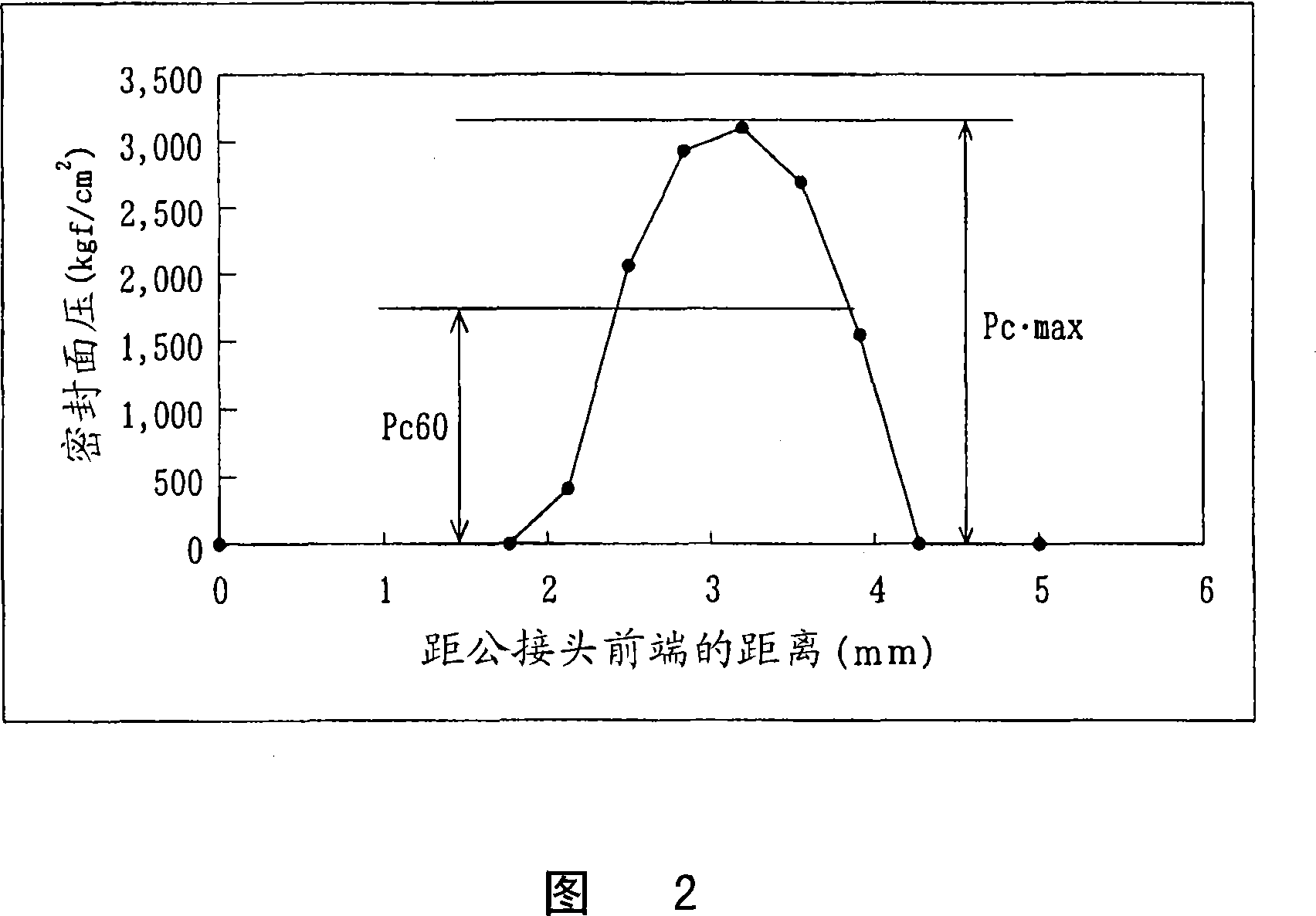
[0035] As mentioned above, conventionally, from the viewpoint of preventing plastic deformation of the sealing part during fitting, the upper limit of the maximum contact surface pressure Pcmax of the sealing part is designed as follows:

[0036] Pcmax>(yield stress σr of threaded joint material).

[0037] However, in reality, even if the maximum contact surface pressure Pcmax of the seal portion is set lower than the yield stress, plastic deformation occurs on the seal portion when the thread portion is fitted, and the thread is re-engaged after the thread is unscrewed. Sometimes, due to this plastic deformation, the seal part cannot obtain a predetermined contact surface pressure Pc.

[0038] In order to prevent this problem, in Embodiment 1 of the pre...

Embodiment 1

[0054] Based on the above-mentioned embodiment, one example of a threaded joint for oil country tubing for an API N80 pipeline system in which outer diameter×pipe wall thickness=3·1 / 2″(88.9mm)×0.254″(6.45mm) will be described. .

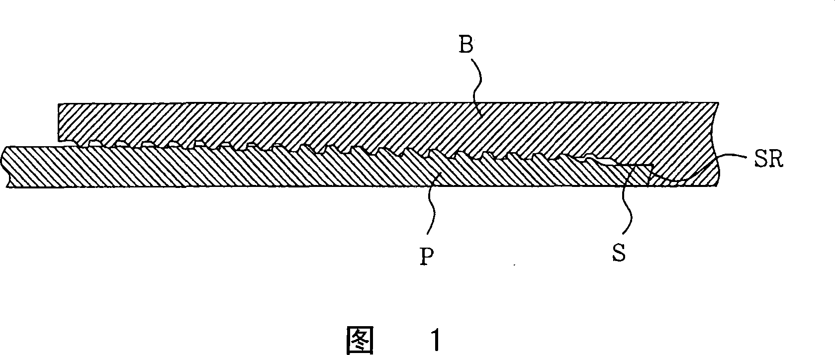
[0055] FIG. 1 is a schematic view showing the basic shape of a threaded joint portion of the first embodiment.

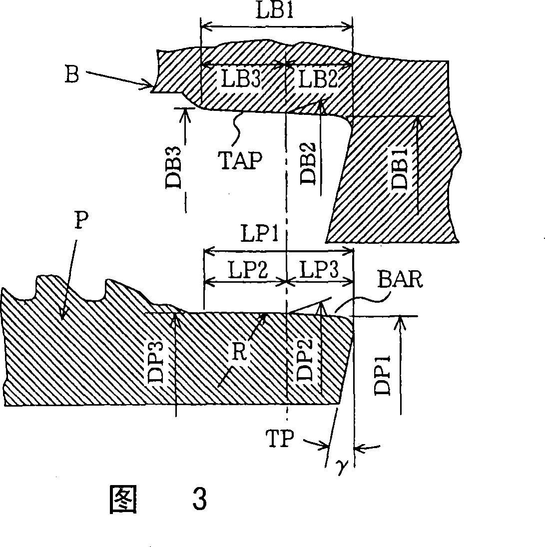
[0056] FIG. 3 is a schematic diagram showing a basic shape of a sealing portion in the first embodiment.

[0057] Fig. 4 is a graph showing the influence of the shoulder angle on the contact pressure.

[0058] Fig. 5 is a schematic view showing the thread cross-sectional shape of the tapered thread of the first embodiment.

[0059] In the figure, P is a male joint with a convex curved sealing part, B is a female joint with a tapered sealing part, S is a sealing part, SR is a shoulder part, TAP is a tapered sealing part, and BAR is a convex curved surface shape , R is the curvature radius of the convex surface shape, TP is the contact po...


PUM


Abstract

A screw coupling for an oil well pipe, comprising a male screw pipe having a seal forming portion in a projectedly curved shape at the tip part of the pipe and a female screw pipe having a tapered seal part. The screw coupling is characterized in that, when the projectedly curved shape is brought into contact with the tapered seal part, a contact surface pressure Pc60 equivalent to 60% of the maximum contact surface pressure Pcmax applied to the contact surface is larger than an inner pressure Pi applied to the screw coupling and smaller than the proportional limit sigmar of the material of the screw coupling. The taper angle thetas of the tapered seal part is thetas >= thetat where the angle of a tapered screw is thetat, and the radius R of the curved surface of the projectedly curved shape is 90 to 170 mm or shorter. The angle thetas is 1.4 to 9.5 DEG at an apex angle, the axial length of the projectedly curved shape is at least 1.5 mm or longer on the front and rear sides of a tangent point, and the surface roughnesses H of the projectedly curved shape and the tapered seal part are 12 s or less.

Description

technical field [0001] The invention relates to threaded joints for oil well pipes. Background technique [0002] Recently excavated oil fields and gas fields are developing towards higher depth and higher pressure. [0003] Along with this, high performance requirements are imposed on threaded joints used in oil country tubular goods due to airtightness and durability. To cope with this problem, a number of special threads have been developed. [0004] The special thread in the prior art is a thread that forms a metal seal through the front end of the pin (male thread) and the inside of the box (box) (female thread) as shown in FIG. 1 . Much development and research has been done on the sealing shape of this particular thread. [0005] As one of them, the screw thread described in JP-A-61-6488 has been developed, which is formed by combining a male joint with a convexly curved sealing surface and a female joint with a tapered sealing surface. The sealing of the tangent ...

Claims


Application Information

Patent Timeline
Patent Type & Authority Applications(China)
IPC IPC(8): F16L15/04E21B17/042F16L15/06
CPCE21B17/042F16L15/004
Inventor 铃木照明
Owner 株式会社美达王
Why Eureka
Try Eureka