
Motion prediction compensation method and motion prediction compensation device

A technology of motion compensation prediction and motion compensation, applied in TV, electrical components, digital video signal modification, etc., can solve problems such as frequent memory access

Inactive Publication Date: 2007-06-06
SONY CORP
View PDF2 Cites 11 Cited by
  • Summary
  • Abstract
  • Description
  • Claims
  • Application Information

AI Technical Summary

Problems solved by technology

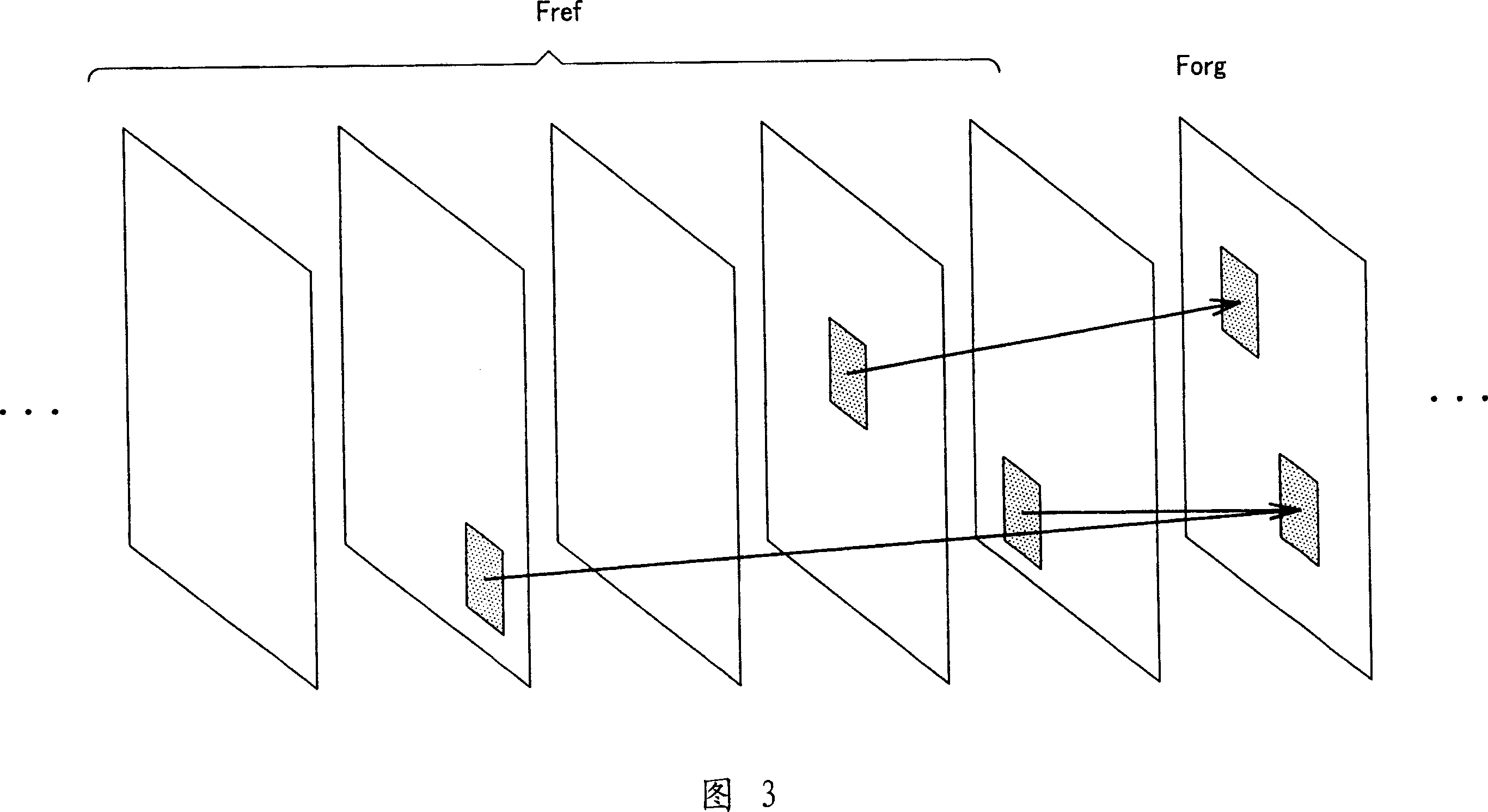
[0052] Also, in the case of being considered in association with an image encoding device (hardware implementation), since motion search processing is performed for each reference frame with respect to all block sizes within a macroblock, access to memory becomes frequent

Method used


Image

  • Motion prediction compensation method and motion prediction compensation device
  • Motion prediction compensation method and motion prediction compensation device
  • Motion prediction compensation method and motion prediction compensation device

Examples


Embodiment Construction

[0071] Preferred embodiments of the present invention will now be described in detail with reference to the accompanying drawings. It should be noted that the present invention is not limited to the following examples, but it is of course possible to arbitrarily change or modify the present invention within the gist without departing from the gist.

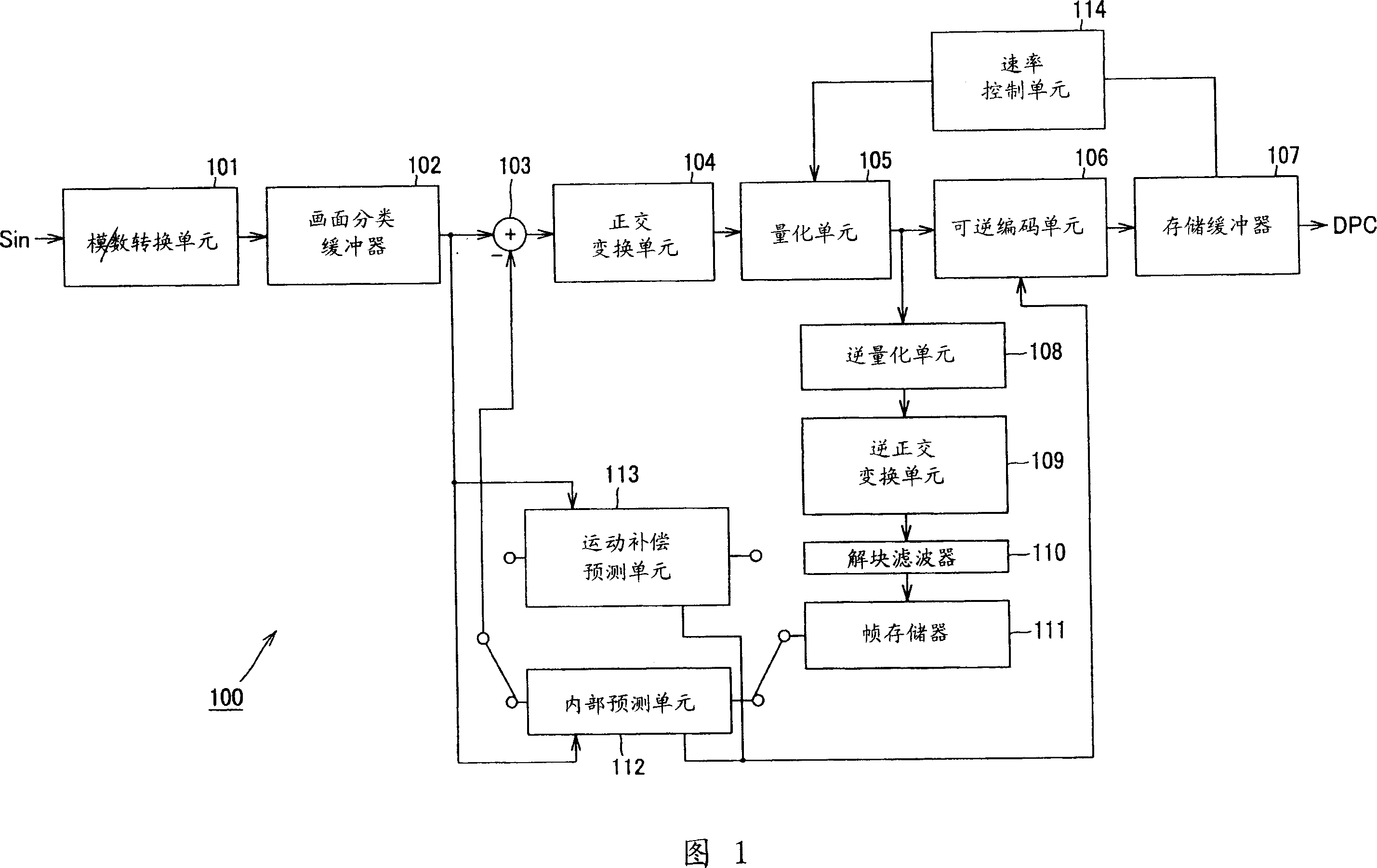
[0072] The present invention is applied to, for example, an image information encoding device 20 configured as shown in FIG. 7 .

[0073]That is, the image information encoding device 20 shown in FIG. 7 includes: an analog / digital conversion unit 1, which is supplied with an image signal Sin as an input; a picture classification buffer 2, which is provided to be digitized by the analog / digital conversion unit 1 image data; adder 3, which is supplied with the image data that has been read out from picture classification buffer 2; intra prediction unit 16; motion compensation prediction unit 17; orthogonal transformation unit 4, whi...


PUM


Abstract

When motion vector is searched based on hierarchical search by designating any one of reference images of plural frames used every respective motion blocks, which have reference images of plural frames and are obtained by dividing an object frame image to be processed among successive frame images, a thinning unit is operative to thin pixels of the motion compensation block having the largest pixel size caused to be uppermost layer among pixel sizes of the motion compensation block to thereby generate a contracted image of lower layer having a predetermined contraction factor; a reference frame determination unit is operative to determine a contracted reference image on the contracted image; a motion compensation prediction unit (1 / N 2 resolution) is operative to search motion vector by using the contracted image thus generated to search; with respect to an image before contraction, motion compensation prediction unit (full resolution) is operative to search motion vector and perform motion compensation prediction by using a predetermined retrieval range designated by motion vector which has been searched at the motion compensation prediction unit (1 / N 2 resolution).

Description

technical field [0001] The present invention relates to a motion compensation prediction method and a motion compensation prediction device (prediction method and device using motion compensation), and is suitable for being applied to an image information coding device for receiving through network media such as discrete cosine image information (bit stream) compressed by orthogonal transform such as Karhunen-Loeve transform and motion compensation etc., as in e.g. MPEG, H.26x, etc., said network media such as broadcast satellite service, cable TV , the Internet and / or mobile phones etc., said image information encoding means or for processing such compressed image information on a memory or storage medium such as an optical / magnetic disk and / or flash memory. [0002] This application claims priority from Japanese Patent Application No. 2004-191937 filed on June 29, 2004, the entire contents of which are hereby incorporated by reference. Background technique [0003] For ex...

Claims


Application Information

Patent Timeline
Patent Type & Authority Applications(China)
IPC IPC(8): H04N7/32H04N19/50H04N19/105H04N19/134H04N19/137H04N19/147H04N19/174H04N19/196H04N19/503H04N19/51H04N19/53H04N19/553H04N19/567H04N19/57H04N19/59H04N19/593H04N19/60H04N19/61H04N19/625H04N19/82H04N19/90H04N19/91
CPCH04N19/006H04N19/00587H04N19/00896H04N19/00672H04N19/51H04N19/82H04N19/53H04N19/567H04N19/176
Inventor 土屋寿治和田彻佐藤数史山田诚
Owner SONY CORP
Learn More