Motion compensation method, picture coding method and picture decoding method

a technology of motion compensation and picture decoding, applied in the field of motion compensation method, picture coding method and picture decoding method, can solve the problems of large load of memory access (access for reading out), deterioration of effect, and reduction of processing amount, so as to reduce the access to reference memory

Active Publication Date: 2011-11-24
GK BRIDGE 1
View PDF3 Cites 52 Cited by
  • Summary
  • Abstract
  • Description
  • Claims
  • Application Information

AI Technical Summary

Benefits of technology

[0017]It is a first object of the present invention to provide a motion compensation method for reducing the access to the reference memory.
[0020]Moreover, since the picture coding apparatus and the picture decoding apparatus motion-compensate with a larger size of the current block to be motion-compensated as the unit, it is possible, for example, to reduce the overhead by access to a picture memory in coding and decoding a B picture using the bi-predictive motion compensation.

Problems solved by technology

On the other hand, when the number of taps of this linear filter is small, the frequency characteristics become worse and therefore the predictive effect deteriorates but the processing amount decreases.
As a result, when reading out the pixel values of the current block to be motion-compensated from the reference memory, there is a problem that the load of memory access (access for reading out) becomes large by referring to the adjacent pixels that are not the target of motion compensation.
Therefore, a problem of overhead becomes more prominent when the size of the current block to be motion-compensated is small.

Method used


Image

  • Motion compensation method, picture coding method and picture decoding method
  • Motion compensation method, picture coding method and picture decoding method
  • Motion compensation method, picture coding method and picture decoding method

Examples


first embodiment

The First Embodiment

[0043]The first embodiment of the present invention will be explained in detail below with reference to the figures.

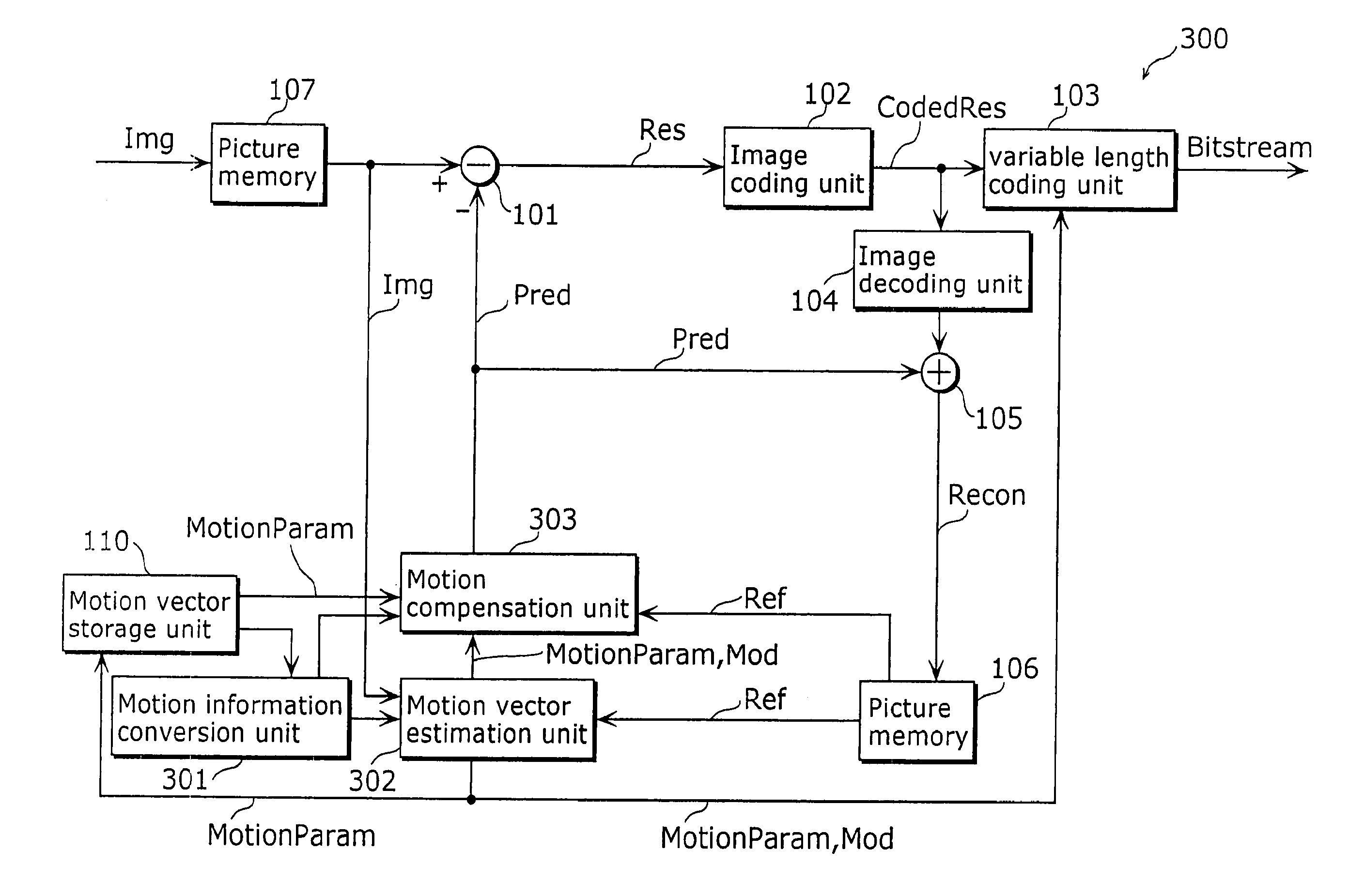
[0044]FIG. 4 is a diagram showing the structure of a picture coding apparatus 300 according to one embodiment using a picture coding method according to the present invention. The picture coding apparatus 300 is a picture coding apparatus that performs motion compensation of a B picture (to be coded) in a larger block size than the block size of motion compensation of a P picture referring to two pictures. The picture coding apparatus 300 includes a difference unit 101, an image coding unit 102, a variable length coding unit 103, an image decoding unit 104, an addition unit 105, a picture memory 106, a picture memory 107, a motion vector storage unit 110, a motion information conversion unit 301, a motion vector estimation unit 302 and a motion compensation unit 303.

[0045]The picture memory 107 stores image data “Img” that represents moving pictures...

second embodiment

The Second Embodiment

[0084]In the Second Embodiment that is explained next, when the current macroblock to be coded or decoded and the macroblock in a subsequent picture which is co-located with the current macroblock are motion-compensated in different sizes, the judgment method for selecting either determining the motion vector of the current block to be motion-compensated to be (0, 0) or determining the motion vector of the current block to be motion-compensated using the motion vectors of the adjacent blocks, is different from the judgment method of the First Embodiment. When the current macroblock and the macroblock in a subsequent picture which is co-located with the current macroblock are motion-compensated in the same block size, motion compensation of a current block to be motion-compensated is performed using the methods explained in FIGS. 6A, 6B, 7 and 8 of the First Embodiment. Consequently, in respect to the structure, the principally different parts between the picture...

third embodiment

The Third Embodiment

[0096]Furthermore, it is possible to easily perform the processing shown in the above embodiments in an independent computing system by recording a program for realizing the picture coding method and the picture decoding method shown in the above-mentioned embodiments onto a storage medium such as a flexible disk.

[0097]FIG. 13 is an illustration of a recoding medium for storing a program for realizing the First and Second Embodiments by a computer system.

[0098]FIG. 13B shows a full appearance of a flexible disk, its structure at cross section and the flexible disk itself; whereas FIG. 13A shows an example of a physical format of the flexible disk as a main body of a storing medium. A flexible disk FD is contained in a case F, a plurality of tracks Tr are formed concentrically from the periphery to the inside on the surface of the disk, and each track is divided into 16 sectors Se in the angular direction. Therefore, as for the flexible disk storing the above-ment...


PUM


Abstract

A picture coding apparatus (300) includes a motion vector estimation unit (302) and a motion compensation unit (303). The motion vector estimation unit (302) selects one method for deriving a motion vector of a block to be motion-compensated, depending on a motion vector of a block located in a corner of a decoded macroblock from among a group of blocks that compose the decoded macroblock corresponding to the current macroblock to be coded and determines the motion vector derived by the selected method for derivation to be a candidate of the motion vector of the current macroblock to be coded. The motion compensation unit (303) generates a predictive image of the block to be motion-compensated based on the estimated motion vector.

Description

1. TECHNICAL FIELD[0001]The present invention relates to a motion compensation method using motion vectors and picture coding, and decoding methods using the motion compensation method.2. BACKGROUND ART[0002]In recent years, accompanied by the development of multimedia applications, it is becoming universal to deal with media information as a whole such as a picture, a voice and a text. At this time, it is possible to deal with the media uniformly by digitizing the entire media. However, the digitized picture has an extremely large amount of data and therefore a technology for compressing picture information is indispensable. On the other hand, it is also important to standardize compression technology to interoperate compressed picture data. As standards of picture compression technology, there are H. 261 and H. 263 of ITU-T (International Telecommunication Standardization Section), MPEG (Moving Picture Experts Group)-1, MPEG-2, MPEG-4 and the like of ISO / IEC (International Standar...

Claims


Application Information

Patent Timeline
Patent Type & Authority Applications(United States)
IPC IPC(8): H04N7/26H04N7/50
CPCH04N19/137H04N19/56H04N19/52H04N19/139H04N19/176H04N19/57H04N19/513H04N19/122H04N19/169H04N19/61H04N19/51H04N19/557H04N19/577H04N19/172H04N19/521H04N19/583H04N19/593
Inventor KADONO, SHINYAKONDO, SATOSHIABE, KIYOFUMI
Owner GK BRIDGE 1
Why Eureka
Try Eureka