Rail fixing device

A technology for fastening devices and rails, applied in the field of supporting bodies, to achieve high elasticity

Inactive Publication Date: 2013-01-02
BWG & K G +3
View PDF11 Cites 3 Cited by
  • Summary
  • Abstract
  • Description
  • Claims
  • Application Information

AI Technical Summary

Problems solved by technology

[0005] The previously known fastening clips of the type described above have the disadvantage of fastening the rails with fastening clips, especially at switche

Method used


Image

  • Rail fixing device
  • Rail fixing device
  • Rail fixing device

Examples


Embodiment Construction

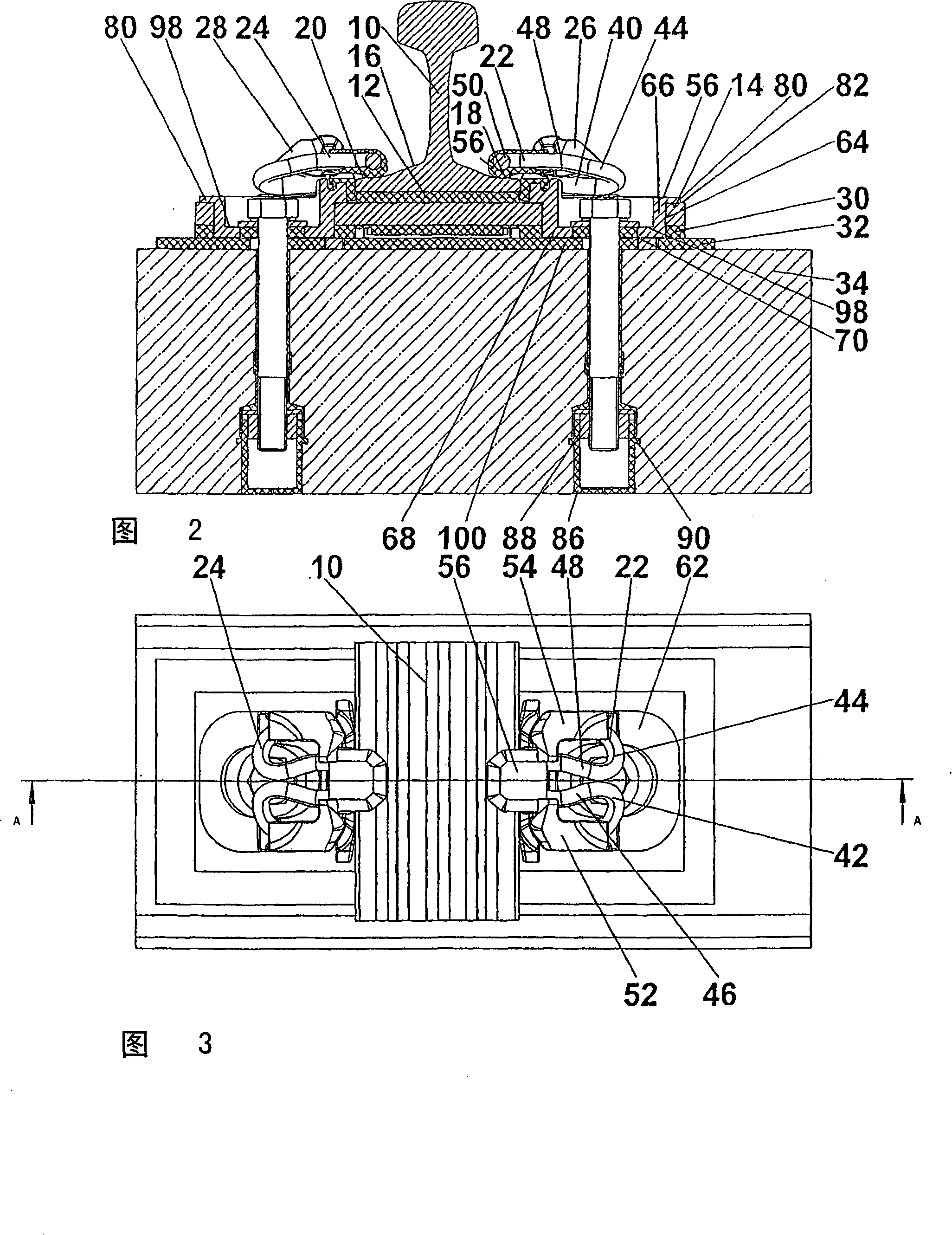
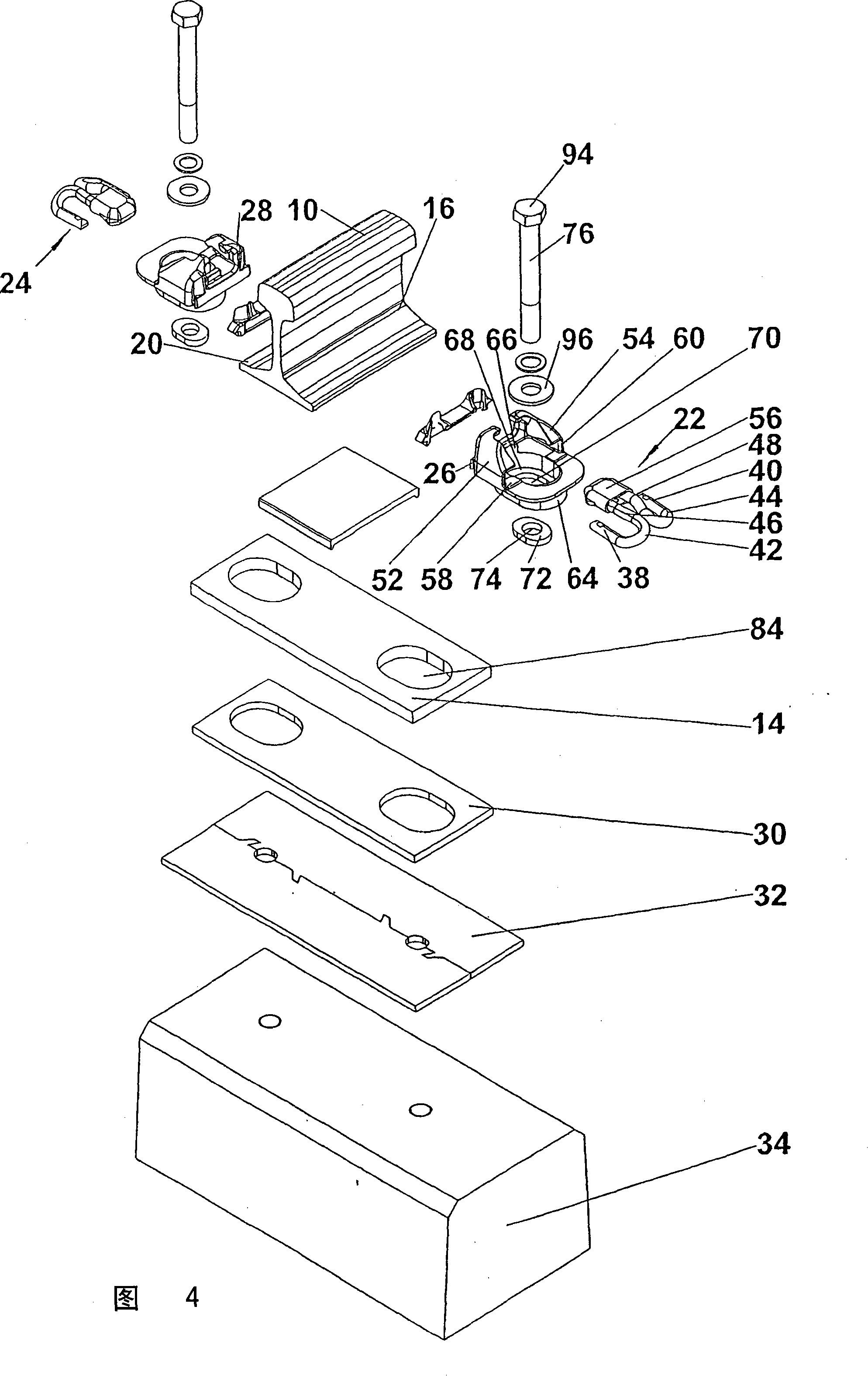
[0056] In principle, the same reference numerals are used for the same elements in the figures in which a fastening device for a rail arranged in a switch is shown. Elastic fastening clips (also called clips) and the brackets accommodating these clips are used to fasten the rails, as these have been described in principle in EP-B-0 619 852, especially in FIGS. 1-5. In this regard, see the relevant publications. Of course, the invention is not limited to the corresponding shape of the fastening clip. Rather, this can also be realized according to the principle of the invention with fastening clips of other geometries and with such fastening clips accommodated by brackets which do not have shoulders for holding the fastening clips, Instead, for example, there is a channel, as is known from the fastening device according to AT-C-350 608 . Reference may also be made expressly to the publications related thereto.

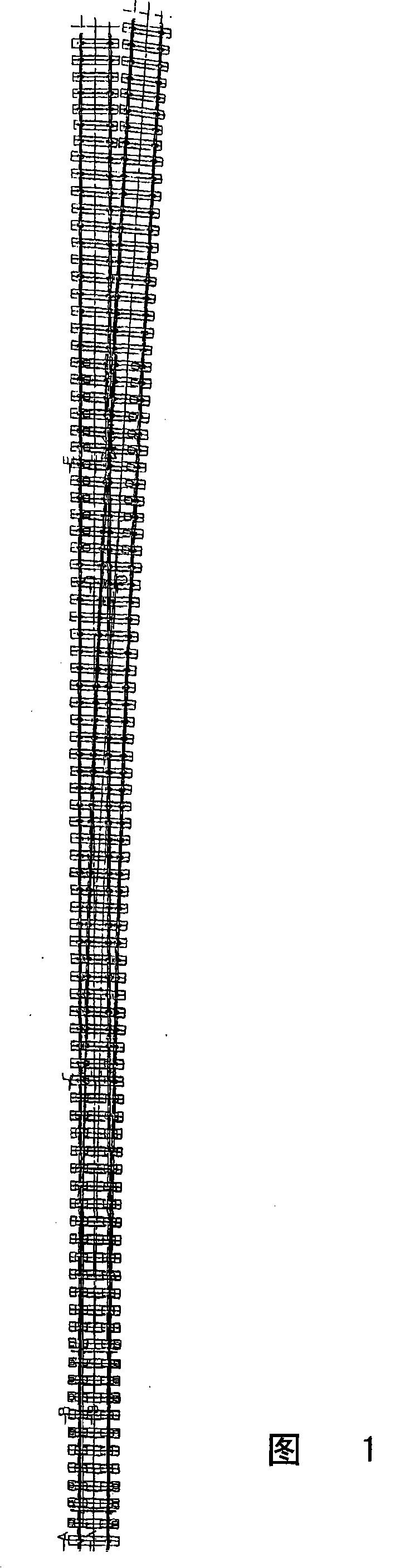
[0057] FIG. 1 shows a position diagram of a simple switch offset...


PUM


Abstract

The invention relates to a rail (10) fixing device with the aid of a tensioning clamp (22, 24) extending from a holding element (26, 28) and is removably arranged on a ribbed plate (14) on which the rail base is mounted. Said ribbed plate is placed on an elastic intermediate layer (30) which is maintained in a required prestressed state by the holding element.

Description

technical field [0001] The invention relates to a device for fastening a rail with track feet to a support, such as a concrete sleeper, with load distribution plates, such as ribs, arranged between the track feet and the support and relative to said support An elastic first intermediate pad that supports the ribs and a second intermediate pad that is also distributed between the first intermediate pad and the support body, it is made of a substantially inelastic material such as a hard plastic, One of the brackets is connected to the support body, from which at least one elastic fastening clip with a plurality of legs protrudes, which is indirectly or directly supported on the rail foot. Background technique [0002] A corresponding device is known from EP-B-0 619 852 . In this case, the fastening clip has an approximately M-shape in plan view and comprises two outer legs and two inner legs, which are each connected to each other by an arcuate section. The outer leg is fix...

Claims


Application Information

Patent Timeline
IPC IPC(8): E01B9/48
Inventor H·霍尼H·-U·迪特泽H·奥斯伯杰J·雷特纳J·波里尔D·R·施利
Owner BWG & K G
Why Eureka
Try Eureka