

Electrically driven camshaft adjuster
A technology of adjusting device and camshaft, applied in valve device, engine element, machine/engine, etc., to achieve the effect of simple structure and improved fail-safety
- Summary
- Abstract
- Description
- Claims
- Application Information
AI Technical Summary
Problems solved by technology
Method used
Image

Examples
Embodiment Construction
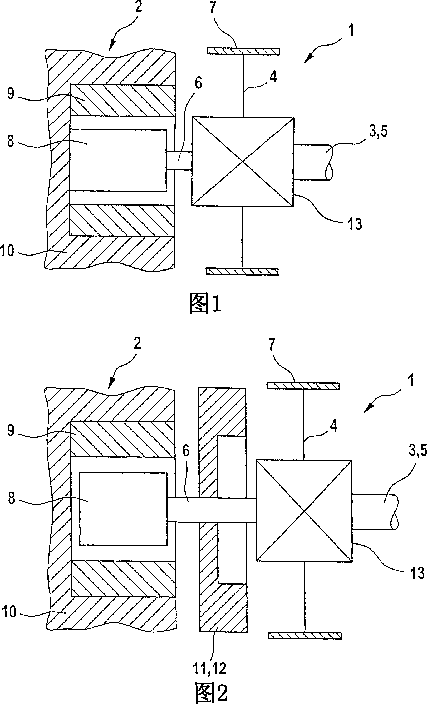
[0042] An embodiment of the invention is shown in FIG. 1 as an adjusting device with a variable-speed gearbox 13 and an adjusting motor 2 consisting essentially of a rotor 8 and a stator 9 . The adjusting device serves to adjust the angular position between the crankshaft and the camshaft 3 in an internal combustion engine (not shown). The transmission gearbox 13 is designed as a three-shaft transmission with a driving element 4 , a driven element 5 and an adjusting shaft 6 . The driving element 4 is fixedly connected with the drive wheel 7 and the crankshaft through an unshown gear, toothed belt or toothed chain. The driven part 5 is fixedly connected to the camshaft 3 and the adjusting shaft 6 to the rotor 8 of the adjusting motor 2 . The stator 9 of the adjusting motor 2 is fixedly connected to the cylinder head 10 and is at rest. Camshaft 3 has a reference position or emergency running position which must be reached for reliable starting and limited operation. Since the...
PUM
 Abstract
Description
Claims
Application Information