Fixed-position stop control apparatus for rotation shaft

A technology of accurate stop control and control device, which is applied in the direction of automatic control device, feedback control, feeding device, etc., and can solve the problem of speed VZ becoming smaller and longer

Active Publication Date: 2007-06-27
FANUC LTD
View PDF1 Cites 33 Cited by
  • Summary
  • Abstract
  • Description
  • Claims
  • Application Information

AI Technical Summary

Problems solved by technology

However, since the specified speed VZ is reduced, the cell interval Z31 is cor

Method used


Image

  • Fixed-position stop control apparatus for rotation shaft
  • Fixed-position stop control apparatus for rotation shaft
  • Fixed-position stop control apparatus for rotation shaft

Examples


Embodiment Construction

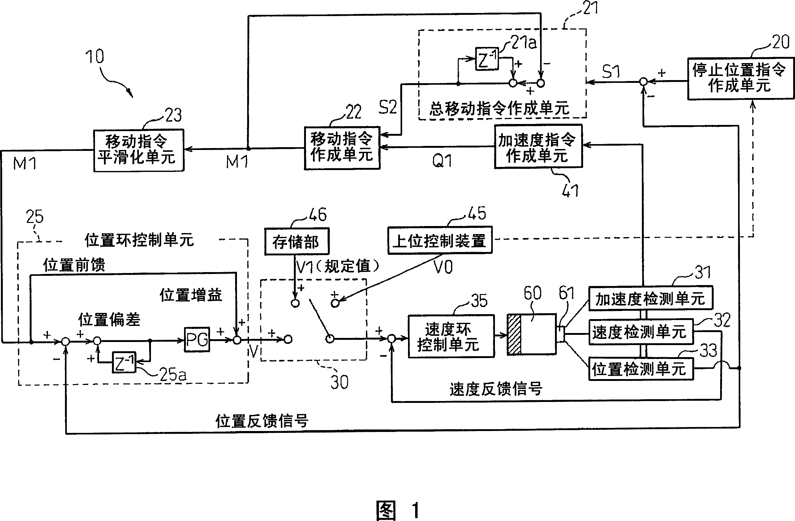
[0036] Hereinafter, embodiments of the present invention will be described with reference to the drawings. In the following drawings, the same reference symbols are assigned to the same components. In order to facilitate understanding, the scales of these drawings are appropriately changed.

[0037] Fig. 1 is a structural diagram of an accurate stop control device for a rotary shaft according to the present invention. The accurate stop control device 10 of the present invention is connected to a motor 60 having a rotating shaft 61 as shown in the figure. The motor 60 is a servo motor or the like used in machine tools such as CNC. As shown in FIG. 1, an acceleration detecting unit 31 for detecting the acceleration of the rotating shaft 61, a speed detecting unit 32 for detecting the speed of the rotating shaft 61, and a mechanical origin for detecting the speed of the rotating shaft 61 are provided in the rotating shaft 61 of the motor 60. The relative position of the fixed ...


PUM


Abstract

A fixed-position stop control apparatus ( 10 ) includes: a move-instruction generating means ( 22 ) for generating a move instruction for each control cycle; a position loop control means ( 25 ) for position controlling a rotation shaft ( 61 ) for each control cycle according to the move instruction generated by the move-instruction generating means; and a speed loop control means ( 35 ) for speed controlling the rotation shaft according to one of a speed instruction generated by a higher level control apparatus ( 45 ) and a predetermined speed instruction, thereby switching the speed control of the rotation shaft by the speed loop control means to the position control of the rotation shaft by the position loop control means. In this fixed-position stop control apparatus, the move instruction generated by the move-instruction generating means has acceleration smaller than the acceleration corresponding to the acceleration and deceleration ability of the rotation shaft. With this arrangement, time required for the rotation shaft to stop at a fixed position can be decreased.

Description

technical field [0001] The present invention relates to an accurate stop control device for a rotary shaft used to stop a rotary shaft of a machine tool or the like at a desired position. Background technique [0002] In the positioning stop control of stopping the rotary axis of a machine tool such as a CNC motor at a desired position, the mechanical origin as a reference is established on the rotary axis at the time of stop, and the reference point is also established on the fixed side. [0003] In the precise stop control device of the rotary axis, first, speed control is performed using one of the speed command created by the host control device and a predetermined speed command. Then, when a desired stop position is used as a stop position command, switching is performed from the speed control of the rotary shaft to the position control of the rotary shaft. Thereafter, the rotary shaft is stopped at the stop position by position control. [0004] Fig. 5 is a graph sho...

Claims


Application Information

Patent Timeline
IPC IPC(8): G05B19/18G05B11/32B23Q15/26G05B19/416G05D3/12H02P3/06
CPCG05B19/19G05B2219/42104
Inventor 岩下平辅秋山隆洋丹羽正一
Owner FANUC LTD
Why Eureka
Try Eureka