Method of controlling an automatic door system

Active Publication Date: 2010-05-13
GLOBE MOTORS
View PDF29 Cites 93 Cited by
  • Summary
  • Abstract
  • Description
  • Claims
  • Application Information

AI Technical Summary

Benefits of technology

[0007]In accordance with another aspect of the invention, a method is provided for controlling an electric motor of an automatic door system. The motor is operatively connected to a door panel to enable the motor to perform a door moving operation for moving the door relative to a door frame. The motor is operable to move the door between open and closed positions using electric power signals delivered to the motor from an electric power supply. The electric power signals being controlled through a motor controller in communication with a system controller, and the system controller is operable to provide control signals to the motor controller for switching power source connections from the power supply to windings of the motor to define motor actuation operations. The method comprises: providing a set point input, the set point input defined as an operator selected parameter provided as an input to the system controller

Problems solved by technology

In addition, in the case of commutator motors, the motor must be of substantial size in order to provide the desired

Method used


Image

  • Method of controlling an automatic door system
  • Method of controlling an automatic door system
  • Method of controlling an automatic door system

Examples


Embodiment Construction

[0021]In the following detailed description of the preferred embodiment, reference is made to the accompanying drawings that form a part hereof, and in which is shown by way of illustration, and not by way of limitation, a specific preferred embodiment in which the invention may be practiced. It is to be understood that other embodiments may be utilized and that changes may be made without departing from the spirit and scope of the present invention.

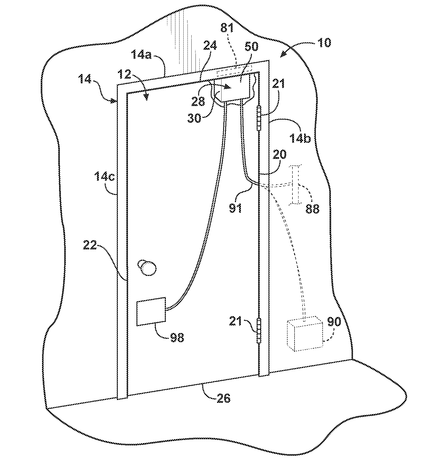
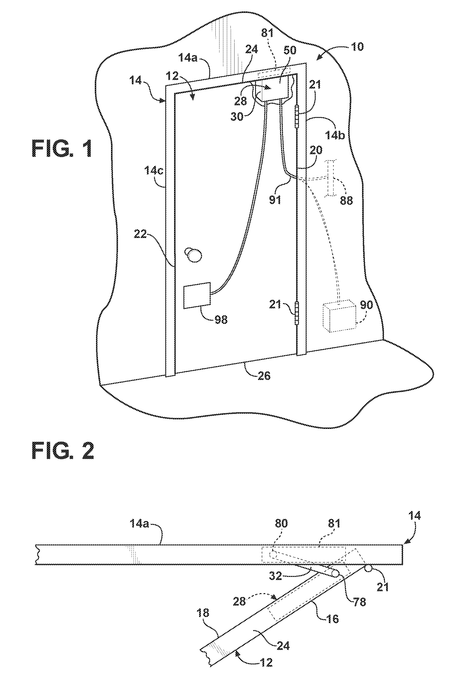
[0022]Referring to FIG. 1, an electric door actuation system 10 is shown for use in controlling movement of a door 12 supported for pivotal movement between open and closed positions in a doorway defined by a door jamb or frame member 14 having a horizontal header 14a and vertical jambs 14b, 14c. The door 12 includes substantially parallel, planar first and second panels 16, 18 (see FIG. 2), opposing inner and outer vertical edge surfaces 20, 22 connecting vertical edges of the first and second panels 16, 18, and opposing upper and lower...


PUM


Abstract

A door position control including an electric door actuator having a motor and a motor controller in communication with a system controller. A motor actuation operation is selected from a plurality of predetermined motor actuation operations to provide control signals to the motor controller for controlling actuation of the motor for control of door movement. Control of door movement is effected with reference to parameters specific to an installation location including an angular sweep of the door between open and closed positions and with reference to an available bus voltage for supplying power to the motor.

Description

CROSS-REFERENCE TO RELATED APPLICATION[0001]This application claims the benefit of U.S. Provisional Application Ser. No. 61 / 113,720, entitled DOOR POSITION CONTROL, filed Nov. 12, 2008, the entire disclosure of which is incorporated by reference herein.FIELD OF THE INVENTION[0002]The present invention relates to power door assemblies and, more particularly, to a power door assembly including a control system for implementing door actuation commands to move a door.BACKGROUND OF THE INVENTION[0003]It is known to provide a door with a door operator to open and / or close the door relative to a door opening. Such door operators may incorporate a motor, such as an electric motor and a drive / actuation mechanism to convert the movement of a motor rotor into movement of the door, such as swinging movement, to open or close the door. Electric motors are commonly used in door operators, and frequently require substantial operating currents and / or voltages to provide the necessary power for cont...

Claims


Application Information

Patent Timeline
IPC IPC(8): E05F15/18G05B11/01H02P6/14G05B11/26E06B3/32E05F15/60
CPCE05Y2400/302E05Y2800/426H02P6/085H02P2205/01E05Y2800/00E05Y2900/132H02P6/28E05F15/60E05F15/63
Inventor GEBHART, STEVEN A.HOSSAIN, SYED A.
Owner GLOBE MOTORS
Why Eureka
Try Eureka