Robot apparatus and method of controlling the same

a robot and apparatus technology, applied in the direction of electric programme control, program control, instruments, etc., can solve the problems of difficult to model after an object or fit the object, and the position control is not suitable for the robot apparatus

Inactive Publication Date: 2009-03-12
SONY CORP
View PDF8 Cites 96 Cited by
  • Summary
  • Abstract
  • Description
  • Claims
  • Application Information

AI Technical Summary

Benefits of technology

[0018]It is desirable to provide a superior robot apparatus in which links are appropriately controlled

Problems solved by technology

The position control is not suitable for flexibly responding an external force and precisely controlling the velocity and acceleration.
Since a robot apparatus carries out a task while physically interacting with various external worlds, for example, grasps an object, the position control is not suitable for the robot apparatus by nature.
In the position control-type robot apparatus, it is difficult to perform a work to model after an object or fit the object.
However, if the force control is used, the driving speed is low, as compared with the position control, and accordingly the work time is extended.
However, the force control method may encounter problems in that: it is assumed the geometric position of a contact surface is known; an unreasonable force is applied due to an error when position control is performed at the contact surface; a control characteristic extremely deviates from its design specification due to a variation in elasticity or frictional coefficient of a contact surface defining a restricted space; and a control system becomes unstable (for example, see Japanese Patent No. 3124519, Paragraphs 0002-0003).
In this case, however, similarly to the above-described mechanical impedance control (N. Hogan: An

Method used


Image

  • Robot apparatus and method of controlling the same
  • Robot apparatus and method of controlling the same
  • Robot apparatus and method of controlling the same

Examples


Embodiment Construction

[0048]Hereinafter, embodiments of the invention will be described in detail with reference to the drawings.

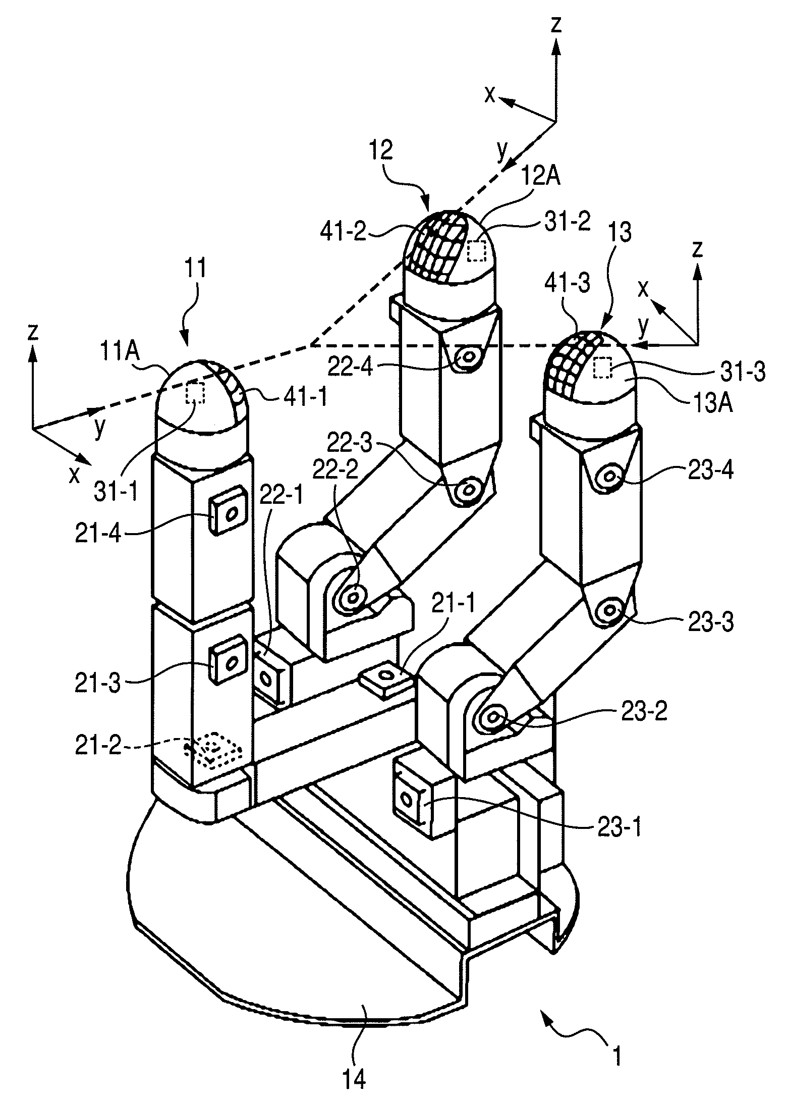
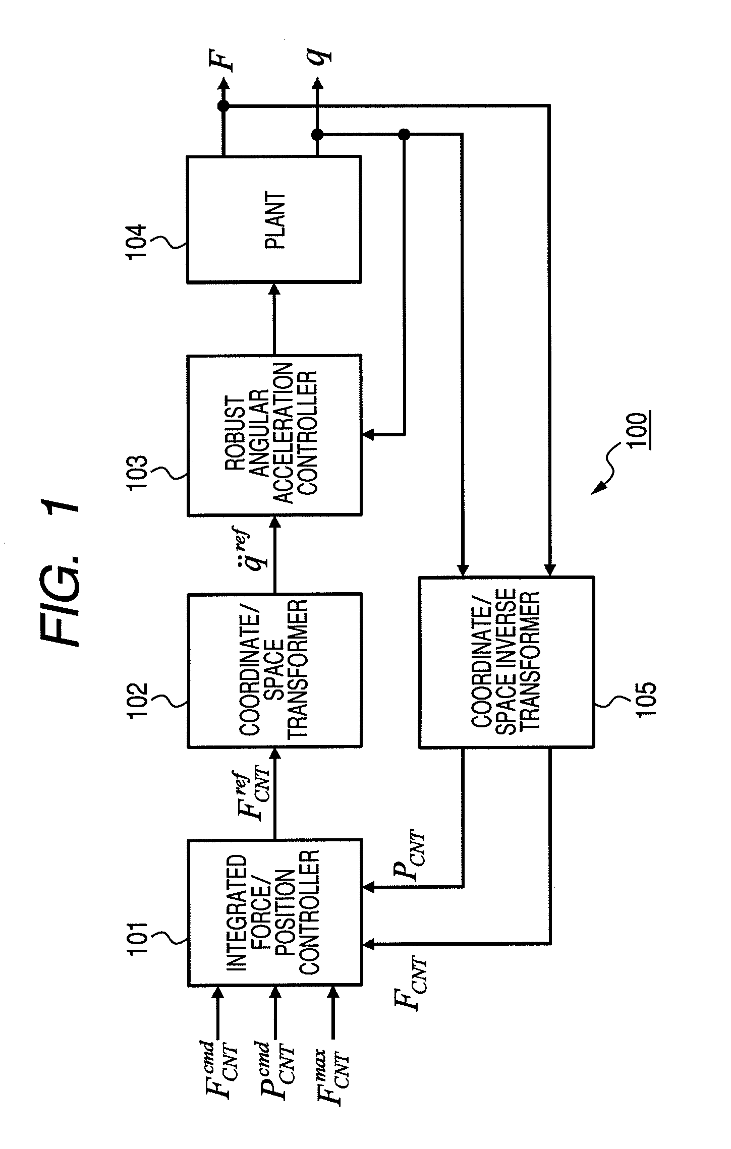
[0049]An embodiment of the invention provides a robot apparatus which has a multi-link structure including a plurality of links and joints serving as link movable sections, and to which a hybrid control system is applied in which position control and force control are unified. That is, at least some of the links are driven by combination of position control and force control. It is necessary to perform the position control and the force control when the robot apparatus approaches an object and when the robot apparatus grasps the object, respectively. The robot apparatus according to the embodiment of the invention performs switching between the position control and the force control when colliding against the object.

[0050]When there is an error in positional information or shape information of an object to contact (for example, an object grasped by a manipulator), the robot app...


PUM

PropertyMeasurementUnit
Forceaaaaaaaaaa

Abstract

A robot apparatus having a multi-link structure including a plurality of links and joints serving as link movable sections, and in which at least some of the links are driven by combination of position control and force control is disclosed. The apparatus includes: position control means for performing the position control on the links, which are driven by position control and force control; position control means with force constraint for placing the force control before the position control so as not to cause the magnitude of an external force to exceed a set value; force control means for performing the force control on the links; and integrated force/position control means for controlling driving of the joints by switching the position control means, the position control means with force constraint, and the force control means, and unifies the position control and the force control.

Description

CROSS REFERENCES TO RELATED APPLICATIONS[0001]The present invention contains subject matter related to Japanese Patent Application JP 2007-235981 filed in the Japanese Patent Office on Sep. 11, 2007, the entire contents of which being incorporated herein by reference.BACKGROUND OF THE INVENTION[0002]1. Field of the Invention[0003]The present invention relates to a robot apparatus such as a manipulator grasping an object or a legged mobile robot having a multilink structure, which includes a plurality of links and joints serving link movable sections, and a method of controlling a robot apparatus. More particularly, the present invention relates to a robot apparatus in which links are controlled by combination of position control and force control, and a method of controlling a robot apparatus.[0004]To be more specific, the present invention relates to a robot apparatus that switches position control and force control when colliding against an object, and a method of controlling a ro...

Claims


Application Information

Patent Timeline
IPC IPC(8): G05B15/00
CPCB25J9/1633G05B2219/39322G05B19/19
Inventor TAKAHASHI, TARO
Owner SONY CORP
Why Eureka
Try Eureka