Optical receiving device, waveform optimization method for optical data signals, and waveform optimization program for optical data signals

a technology of optical data signals and waveform optimization methods, applied in the direction of digital signal error detection/correction, recording signal processing, instruments, etc., can solve the problems of increasing waveform deterioration, deterioration of optical receive waveform, accumulation of noise, etc., to optimize optical waveform, optimize optical data signal waveform, optimize optical waveform

Inactive Publication Date: 2006-10-17
NEC CORP
View PDF14 Cites 94 Cited by
  • Summary
  • Abstract
  • Description
  • Claims
  • Application Information

AI Technical Summary

Benefits of technology

[0011]In light of these circumstances, the first object of the present invention is to provide an optical receiving device with capabilities for dispersion equalization, which can optimize optical waveform by controlling the dispersion characteristics of a variable dispersion equalizer for controlling the disperse value to remain at a desired value, a method for optimizing the waveform of optical data signals, and a program for optimizing the waveform of optical data signals.

Problems solved by technology

One example of factors that may cause a deterioration in optical receive waveform is the accumulation of noise, resulting from ASE (amplified spontaneous emission) from optical fiber amplifiers.
In WDM, such an increase in waveform deterioration is often caused by crosstalk interference from adjacent channels.
In order to further improve receiving sensitivity, however, these provisions are not sufficient, but the compensation of waveform deterioration itself must be addressed.
As far as conventional optical transmission lines are concerned, the issue of the light receiving power is negligible in practical use.
Furthermore, for a typical optical transmission system incorporating an optical amplifier and WDM, it is difficult to maintain the quality of a transmission line by using a conventional discrimination circuit with a fixed decision threshold position.
This is because the increased number of factors that are responsible for deterioration in optical receive waveform as described above causes a discrimination circuit to inherently suffer from a curve (floor) in error rate characteristic (see the upper diagram of FIG. 37).

Method used


Image

  • Optical receiving device, waveform optimization method for optical data signals, and waveform optimization program for optical data signals
  • Optical receiving device, waveform optimization method for optical data signals, and waveform optimization program for optical data signals
  • Optical receiving device, waveform optimization method for optical data signals, and waveform optimization program for optical data signals

Examples


first embodiment

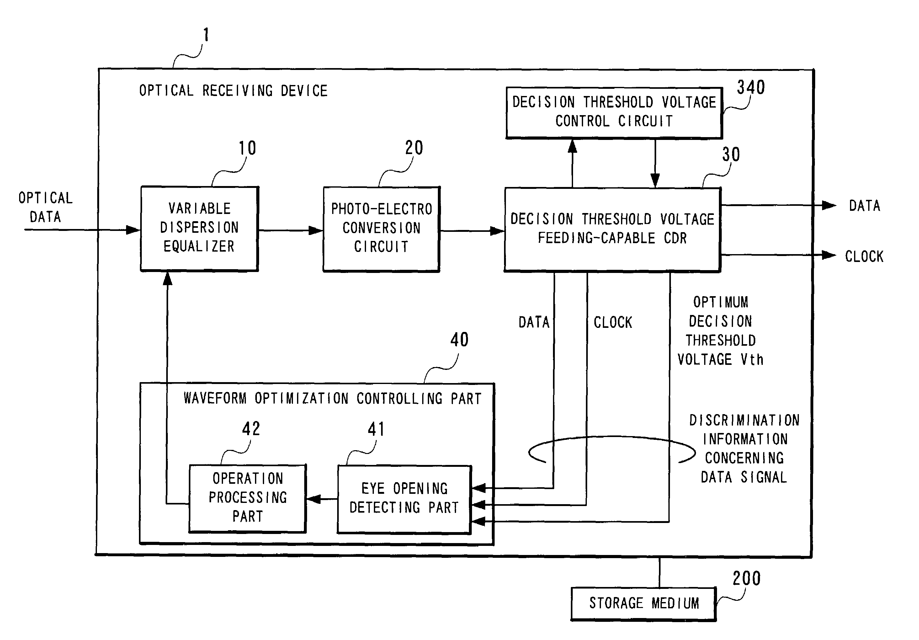
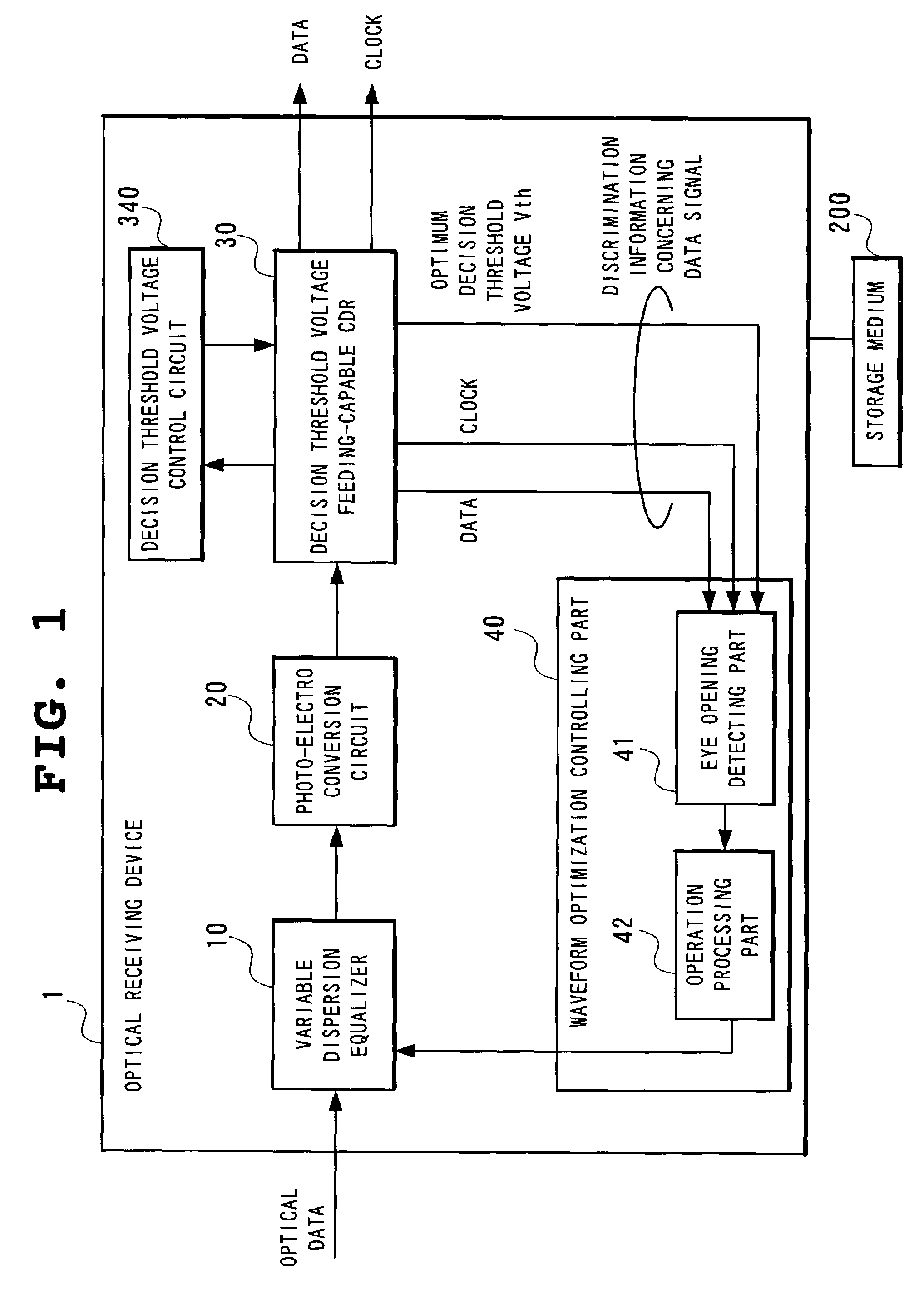
[0116]While the present invention can be applied to both optical receiving devices and repeating installations, this section will specifically describe the first embodiment featuring its application to an optical receiving device. FIG. 1 is a block diagram showing the configuration of an optical receiving device according to the first embodiment of the present invention.

[0117]According to this embodiment, an optical receiving device 1 comprises a variable dispersion equalizer 10, a photo-electro conversion circuit 20, a decision threshold voltage feeding-capable CDR 30, and a waveform optimization controlling part 40. The waveform optimization controlling part 40 includes an eye opening detecting part 41 and an operation processing part 42.

[0118]As shown in FIG. 8, the variable dispersion equalizer 10 is characterized by its ability to change the inclination of wavelength dispersion characteristics by controlling the temperature of the dispersion equalizer through use of a Peltier d...

second embodiment

[0160]The second embodiment of the present invention will now be described with reference to FIGS. 13, 14, and 15.

[0161]FIG. 13 is a diagram illustrating the control algorithm for the operation processing part 42 according to the second embodiment. FIG. 14 shows a flow chart realizing such control algorithm operation. FIG. 15 is a diagram showing the relationship between the dispersed value D and the size of the eye opening P.

[0162]The second embodiment adopts another idea of Step 903 in FIG. 9, which determines whether to increment or decrement the dispersed value D by comparing between the current and previous measurements of the size of the eye opening.

[0163]As with the first embodiment, this embodiment begins with the minimum value D0 of the dispersed value D and increments it by ΔD with every increase (improvement) in the size of the eye opening.

[0164]This embodiment differs from the first embodiment in that, as seen from Step 903B for the control algorithm in FIG. 13, the algo...

third embodiment

[0173]The third embodiment of the present invention will now be described with reference to FIGS. 16, 17, and 18.

[0174]FIG. 16 is a diagram illustrating the control algorithm for the operation processing part 42 according to the third embodiment. FIG. 17 is a flow chart realizing such control algorithm operation. FIG. 18 is a diagram showing the relationship between the dispersed value D and the size of the eye opening P.

[0175]The third embodiment adopts yet another idea for Step 903 in FIG. 9, which determines whether to increment or decrement the dispersed value D by comparing between the current and previous measurements of the size of the eye opening.

[0176]This embodiment is similar to the second embodiment in that the algorithm begins with the minimum value D0 of the dispersed value D and increments it by ΔD with every increase (improvement) in the size of the eye opening and that the algorithm switches the operational direction from increase to decrease if the size of the eye ...


PUM


Abstract

This optical receiving device for discriminating and recovering a data signal, which results from converting an optical signal input through a dispersion equalizer into an electrical signal and amplifying it to a pre-determined amplitude, by using a clock and data recovery circuit for discriminating a data signal at the decision point controlled to achieve the optimum position controls the dispersion characteristics of a dispersion equalizer so that the error count in the recovered data signal by using a clock and data recovery circuit will be minimized by controlling the eye pattern of the data signal which has been amplified to a pre-determined amplitude.

Description

BACKGROUNDS OF THE INVENTION[0001]1. Field of the Invention[0002]The present invention relates to an optical receiving device, a waveform optimization method for optical data signals, and a waveform optimization program for optical data signals. More particularly, the present invention relates to an optical receiving device that is designed to minimize waveform deterioration in optical data signals, a waveform optimization method for optical data signals, and a waveform optimization program for optical data signals.[0003]2. Description of the Related Art[0004]Recent optical transmission systems incorporating optical amplifiers and the technology of WDM (wavelength division multiplexing) have more factors that may cause a deterioration in optical receive waveform than conventional optical transmission systems.[0005]One example of factors that may cause a deterioration in optical receive waveform is the accumulation of noise, resulting from ASE (amplified spontaneous emission) from op...

Claims


Application Information

Patent Timeline
Patent Type & Authority Patents(United States)
IPC IPC(8): H04B10/06H04B10/18H04B10/2507H04B10/07H04B10/2513H04L7/00
CPCH04B10/25133H04B10/67H04B10/695H04L25/063H04B2210/252
Inventor TATEYAMA, TETSUOKURIYAMA, TAKASHIMATSUMOTO, YOSHIHIRO
Owner NEC CORP
Why Eureka
Try Eureka