Apparatus for data recovery in a synchronous chip-to-chip system

a chip-to-chip system and data recovery technology, applied in the field of signal communication, can solve the problems of significant compensation, loss of timing margin, and dependence on timing errors, and achieve the effect of reducing the sampling errors of data communicated and improving the waveform

Inactive Publication Date: 2008-07-31
RAMBUS INC
View PDF27 Cites 12 Cited by
  • Summary
  • Abstract
  • Description
  • Claims
  • Application Information

AI Technical Summary

Benefits of technology

[0006]In accordance with an aspect of the present invention, an apparatus is disclosed that can reduce sampling errors for data communicated between devices. The apparatus uses phase information acquired from a timing reference signal such as a strobe signal to align a data-sampling signal for sampling a data signal that was sent along with the timing reference signal. The data-sampling signal may be provided by adjustably delaying a clock signal according to the phase information acquired from the strobe signal. The data-sampling signal may also have an improved waveform compared to the timing reference signal, including a fifty- percent duty cycle and sharp transitions. The phase information acquired from the timing reference signal may also be used for other purposes, such as aligning received data with a local clock domain, or transmitting data so that it arrives at a remote device in synchronism with a reference clock signal at the remote device.

Problems solved by technology

Unfortunately, because a delayed version of the data strobe signal is ultimately used to control the sampling of the DQ lines (a technique referred to herein as direct strobing), any transient sources of timing error in the data strobe signal such as intersymbol interference (ISI) and cross-talk, or data-dependent timing errors resulting from mismatched rising and falling edge rates are not significantly compensated by the variable delay circuit 15 and instead appear as timing jitter at the sample control inputs of the data receiver.
As discussed above, such inaccuracy in the sampling point translates to lost timing margin and ultimately to reduced data transfer rates.

Method used


Image

  • Apparatus for data recovery in a synchronous chip-to-chip system
  • Apparatus for data recovery in a synchronous chip-to-chip system
  • Apparatus for data recovery in a synchronous chip-to-chip system

Examples


Embodiment Construction

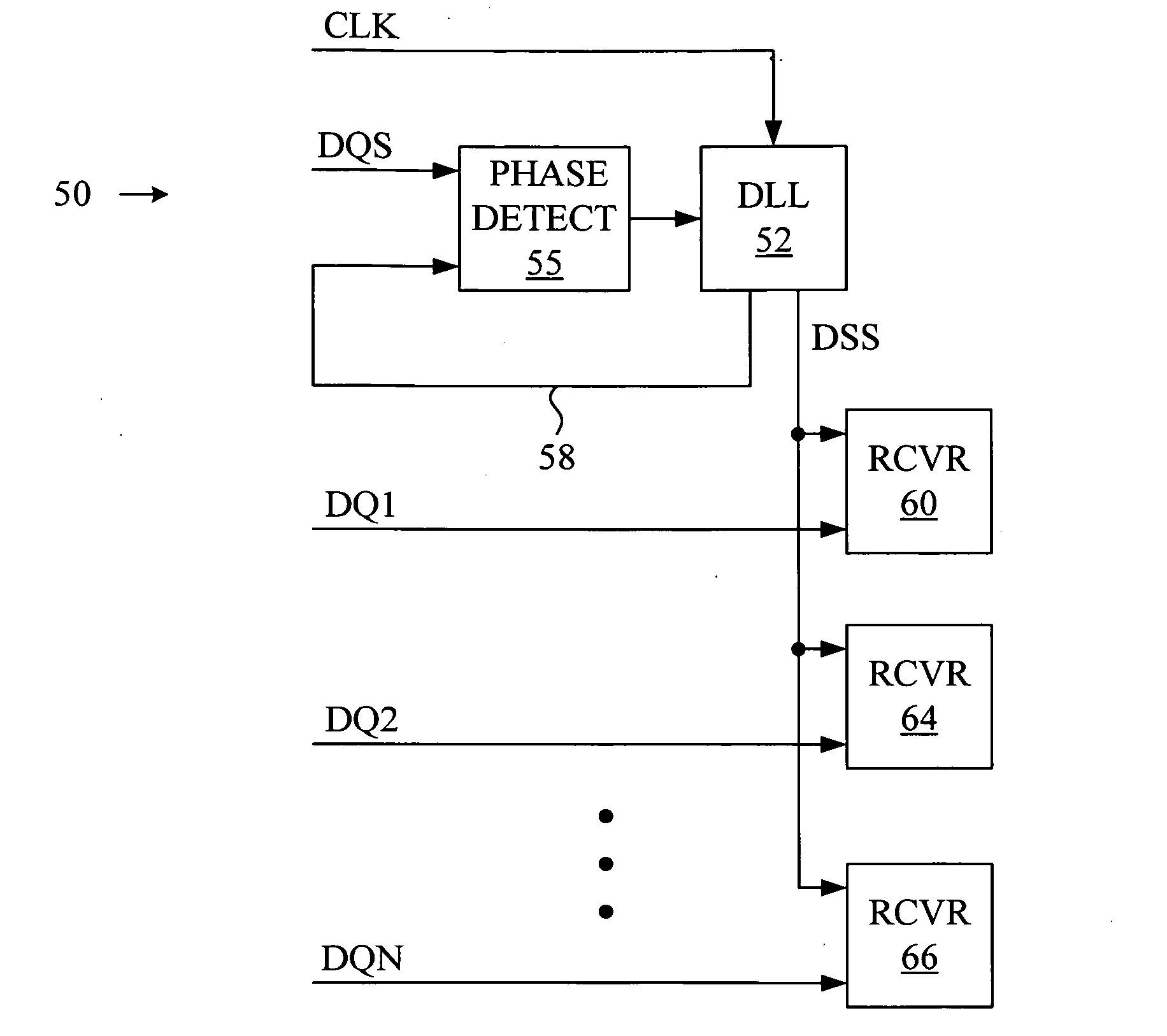
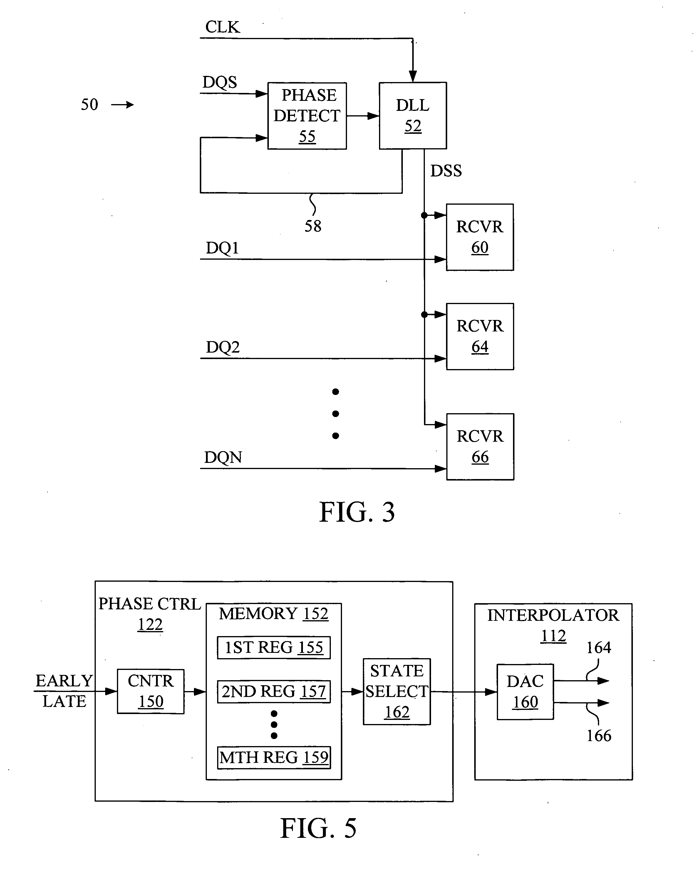
[0017]FIG. 3 shows a diagram of a data-sampling apparatus 50 that creates a data-sampling signal on data-sampling line DSS for sampling data signals received on data lines DQ1-DQN with receivers 60, 64 and 66. The data-sampling signal is output by a DLL 52 that adjusts the phase of a clock signal on clock line CLK in accordance with phase information acquired from a strobe signal received on strobe line DQS. The phase information is acquired by comparing, at a phase detector 55, the strobe signal received on strobe line DQS with the signal output by DLL 52 on phase-lock line 58. Thus, unlike the direct strobing of the prior art, in which the strobe signal is used for sampling data signals, in accordance with the present invention the strobe signal is used to adjust the phase of a data-sampling signal, and the data-sampling signal is instead employed to sample data signals.

[0018]As discussed below, embodiments of the present invention may be used with timing reference signals other t...


PUM


Abstract

An apparatus that reduces sampling errors for data communicated between devices uses phase information acquired from a timing reference signal such as a strobe signal to align a data-sampling signal for sampling a data signal that was sent along with the timing reference signal. The data-sampling signal may be provided by adjustably delaying a clock signal according to the phase information acquired from the strobe signal. The data-sampling signal may also have an improved waveform compared to the timing reference signal, including a fifty percent duty cycle and sharp transitions. The phase information acquired from the timing reference signal may also be used for other purposes, such as aligning received data with a local clock domain, or transmitting data so that it arrives at a remote device in synchronism with a reference clock signal at the remote device.

Description

TECHNICAL FIELD[0001]The present invention relates to the field of signal communications and more particularly to high-speed transfer of information within and between integrated circuit devices using electrical signaling.BACKGROUND[0002]In modern electronic systems, data and control information are transferred between various subsystems using extremely short-lived electrical signals. For example, in high-speed memory systems, a data signal from a memory controller to a memory device may be valid at the input of the memory device for only a nanosecond or less; less time, in some cases, than the propagation time of the data signal on the signaling path between the memory controller and the memory device. In any such high-speed signaling system, the ability of the receiving device to sample the data signal at a precise instant within the valid data interval (the “data eye”) is often a critical factor in determining how brief the data eye may be and, consequently, the overall data tran...

Claims


Application Information

Patent Timeline
Patent Type & Authority Applications(United States)
IPC IPC(8): H03D3/24H04L7/02G06F1/10H03L7/07H03L7/081H04L7/033
CPCG06F1/10G11C7/1087G11C7/222G11C7/10H03L7/07H03L7/0814H04L7/0337G11C2207/107G11C7/04G11C11/4076G11C11/4091
Inventor BEST, SCOTT C.WARMKE, RICHARD E.ROBERTS, DAVID B.LAMBRECHT, FRANK
Owner RAMBUS INC
Why Eureka
Try Eureka