Circuit protection method, protection circuit and circuit protection device

A circuit protection and circuit technology, applied in the fields of protection circuits, circuit protection devices, and circuit protection methods, can solve problems such as slow response, malfunction of protection components, and inaccurate comparison results, and achieve the effect of avoiding damage and improving accuracy.

Active Publication Date: 2019-04-05
KUNSHAN GO VISIONOX OPTO ELECTRONICS CO LTD
View PDF10 Cites 5 Cited by
  • Summary
  • Abstract
  • Description
  • Claims
  • Application Information

AI Technical Summary

Problems solved by technology

However, in the above-mentioned solution, it is determined whether there is an overcurrent in the circuit by comparing the sampling voltage with the voltage threshold value, regardless of the influence of the change of the current, the comparison result is not accurate enough, and it is easy to cause a slow response to the sudden increase of the overcurrent and easily cause protection. Component malfunction, etc.

Method used


Image

  • Circuit protection method, protection circuit and circuit protection device
  • Circuit protection method, protection circuit and circuit protection device
  • Circuit protection method, protection circuit and circuit protection device

Examples


Embodiment 1

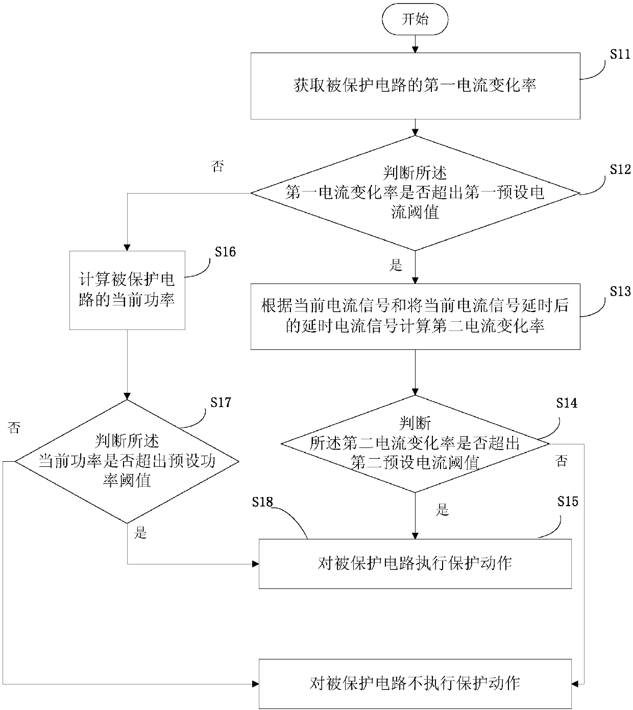
[0031] This embodiment provides a circuit protection method, which is suitable for overcurrent protection of the related circuits of the power supply chip of the AMOLED screen, such as figure 1 As shown, the method can be implemented by software or by hardware circuit. In this embodiment, the circuit protection method is implemented by software. A sampling resistor is set in the output circuit of the power supply chip to collect data in the circuit. The current value is input into the controller, and the controller executes the following method to realize circuit protection through software, including the following steps:

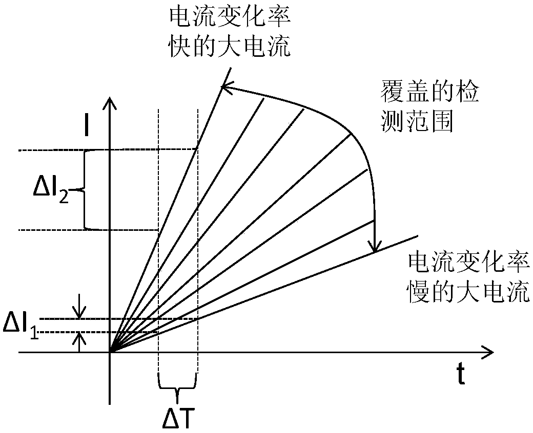
[0032] S11: Obtain the first current change rate of the protected circuit, that is, detect the current change rate of the protected circuit in real time. Specifically, the large current (ie, overcurrent) generated by short-circuiting between different power sources and the ground, due to the differences in the respective circuits, is large The rate of chang...

Embodiment 2

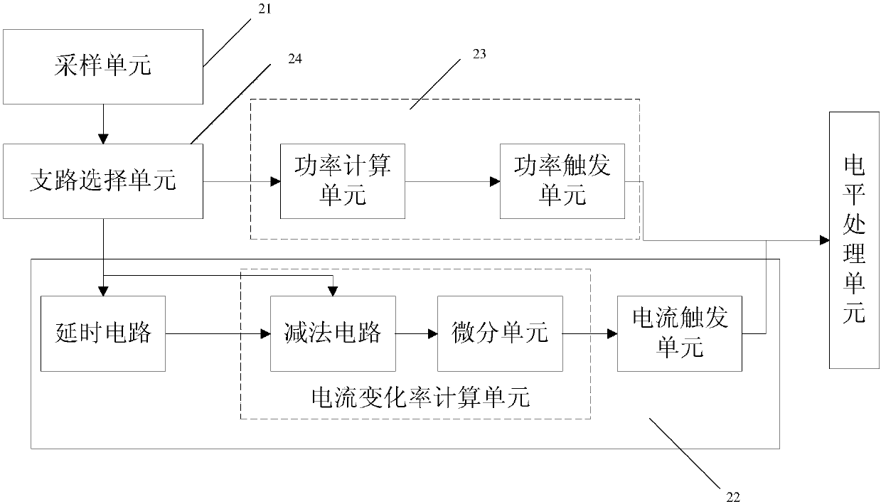
[0054] A protection circuit is provided in this embodiment, and the protection of the power supply circuit is realized by means of a hardware circuit. This method is the same as the method in Embodiment 1, but it is realized by a hardware circuit in this embodiment. The protection circuit includes a sampling unit 21, a first branch 22, a second branch 23, and a branch selection unit 24, such as image 3 As shown, specifically:

[0055] The sampling unit 21 is used for sampling the current signal of the circuit to be protected.

[0056] The first branch 22 includes a delay circuit, a current rate of change calculation unit, and a current trigger unit. The current current signal output by the sampling unit is processed by the delay circuit to output a delayed current signal. The delayed current signal and the current current signal Input the current change rate calculation unit to calculate the third current change rate, and send the third current change rate to the current tri...

Embodiment 3

[0064] This embodiment provides a circuit protection device, which is a device corresponding to the circuit protection method in Embodiment 1, such as Figure 4 shown, including:

[0065] The obtaining module 31 is configured to obtain the first current change rate of the protected circuit; for details, refer to the detailed description of step S11 in Embodiment 1.

[0066] The first judging module 32 is configured to judge whether the first current rate of change exceeds a first preset current threshold; for details, refer to the detailed description of step S12 in Embodiment 1.

[0067] Delay calculation module 33, used to calculate the second current change rate according to the current current signal and the delayed current signal after the current current signal is delayed when the first current change rate exceeds the first preset current threshold; specifically Refer to the detailed description of step S13 in Embodiment 1.

[0068] The second judging module 34 is conf...


PUM


Abstract

The invention provides a circuit protection method, a protection circuit and a circuit protection device. The current change rate of a protected circuit is detected in real time, and if the current change rate is larger than the first preset current change rate, it proves that a suddenly-increased over-current may be generated in the protected circuit; the change rate of the second current can becalculated in a time-delay mode, and a protection action is performed on the protected circuit according to the value of the second current change rate; and if the first current change rate detectedin real time is not larger than the first preset current change rate, whether the protection action needs to be executed or not is determined by calculating the sampling power of a sampling circuit inthe protected circuit, so that the situation that the protected current cannot work normally due to over-current is avoided, whether over-current exists or not is determined through a two-layer judgment mechanism, and the accuracy of the over-current protection scheme is improved.

Description

technical field [0001] The invention relates to the field of display technology, in particular to a circuit protection method, a protection circuit and a circuit protection device. Background technique [0002] When the power supply chip supplies power to the AMOLED (Active-matrix organic light emitting diode, active matrix organic light-emitting diode) screen, it is easy to short circuit with the ground, and a large current will be generated during the short circuit, which will cause the power supply There is a problem with the power supply stability of the chip itself and the entire circuit, which in turn affects the normal display function of the AMOLED screen. [0003] In view of the above problems, overcurrent protection is generally used for the circuit. In the prior art, the most common method of overcurrent protection is: by connecting the sampling resistor in series with the protected circuit, and then sampling the protected circuit to form a sampling voltage. Then...

Claims


Application Information

Patent Timeline
Patent Type & Authority Applications(China)
IPC IPC(8): H02H3/08
CPCH02H3/08
Inventor 孙志松张小宝葛明伟王峥
Owner KUNSHAN GO VISIONOX OPTO ELECTRONICS CO LTD
Why Eureka
Try Eureka