Flat-panel display apparatus

A display device, flat-type technology, applied in identification devices, cooling/ventilation/heating renovation, instruments, etc., can solve problems such as reduced adhesion and reduced thermal conductivity, and achieves the effect of superior cost characteristics

Inactive Publication Date: 2007-06-27
HITACHT MAXELL LTD
View PDF4 Cites 0 Cited by
  • Summary
  • Abstract
  • Description
  • Claims
  • Application Information

AI Technical Summary

Problems solved by technology

At this time, air bubbles exist between the thermally conductive member and the PDP, or between the thermally conductive member and the chassis member, which reduces the adhesion between the thermally conductive member and the PDP or the thermally conductive member and the chassis member, and reduces the thermal conductivity.

Method used


Image

  • Flat-panel display apparatus
  • Flat-panel display apparatus
  • Flat-panel display apparatus

Examples


Embodiment 1

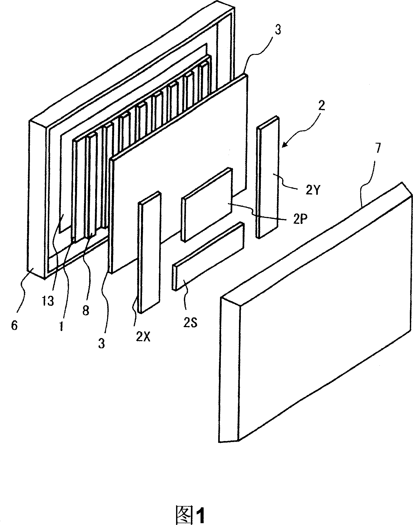
[0040] FIG. 1 is an exploded perspective view showing the configuration of main parts of a plasma display device according to Embodiment 1 of the present invention.

[0041]In FIG. 1 , the housing for accommodating the PDP 1 is composed of a front frame 6 in which a front cover 13 made of glass or the like is disposed in an opening, and a metal rear cover 7 . For example, the PDP 1 is bonded to the front surface of the chassis member 3 made of aluminum or the like via the thermally conductive member 8, the PDP 1 is held, and a plurality of circuit boards 2 for display driving the PDP 1 are mounted on the rear side of the chassis member 3. The thermally conductive member 8 can efficiently transfer the heat generated in the PDP 1 to the chassis member 3 to dissipate heat. The chassis member 3 functions as a holding member for holding the above-mentioned PDP 1 to dissipate heat generated from the PDP 1 to cool the PDP 1 . In addition, the circuit board 2 includes an X sustaining...

Embodiment 2

[0076] In Example 1, the thermally conductive member (HM adhesive) was applied in a rectangular shape with a predetermined width at predetermined intervals along the longitudinal direction of the PDP (horizontal direction of the screen), but the present invention is not limited thereto.

[0077] 7 is a schematic view of the thermally conductive member coated on the back side of the PDP of Example 2 viewed from the thermally conductive member side.

[0078] In FIG. 7, the thermally conductive member 8 is applied in a strip-shaped rectangular shape parallel to the short side of the PDP (vertical direction of the screen) at predetermined intervals W along the long side direction of the PDP (horizontal direction of the screen) (hereinafter, called "rectangular shape"). However, in this example, unlike Example 1, the luminance is dispersed at a predetermined interval WV (for example, WV=10mm or less when the coating thickness is 0.5mm) that does not cause brightness unevenness in t...

Embodiment 3

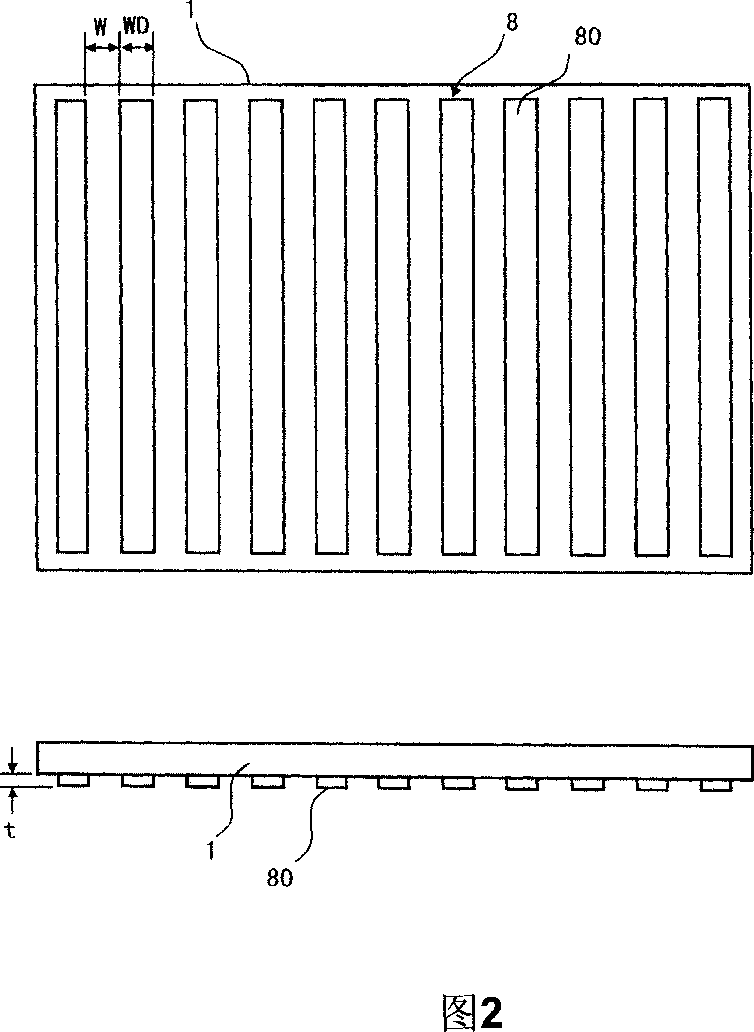
[0081] Embodiment 3 of the present invention will be described below. 8 is a schematic view of the thermally conductive member coated on the back side of the PDP of Example 3 viewed from the thermally conductive member side.

[0082] In Example 1, the thermally conductive member (HM adhesive) was applied in a rectangular shape with a predetermined width at predetermined intervals along the longitudinal direction of the PDP (horizontal direction of the screen), but in this embodiment, as shown in FIG. As shown, the width WD of the rectangular thermally conductive portion 82 is made larger on the screen center side and smaller on the screen edge side.

[0083] As described above, when a person looks at a screen, the viewpoint usually coincides with the center of the screen, so it is necessary to take care not to cause brightness unevenness in the center of the screen. Therefore, by increasing the width WD of the rectangular heat conduction portion 82 in the central portion of t...


PUM


Abstract

According to the present invention, the amount of usage of a heat conductive member for fixing a self-luminous flat display panel to a metallic chassis member disposed at the back of the display panel is reduced in the thickness direction as well as in the surface direction. The invention further provides a technique for efficiently radiating heat from the display panel, suppressing cost increase. To this end, in the invention, the heat conductive member is a hot-melt adhesive having adhesion at room temperature and filled with a heat conduction imparting agent, and the display panel is fixed to the chassis member by a plurality of heat conducting sections of the heat conductive member formed discretely ranging from 0.3 to 0.8 mm in thickness.

Description

technical field [0001] The present invention relates to a flat display device using a flat display panel in which self-luminous pixels are arranged between opposing substrates, and more particularly, to a display device in which efforts are made to efficiently dissipate heat from the display panel. Background technique [0002] Examples of self-luminous flat display panels include plasma panels (hereinafter abbreviated as "PDP"), electron emission element display panels, organic EL panels, and the like. In addition, there are also LED display panels in which LED elements are arranged two-dimensionally, for example. [0003] In a display device using a self-luminous panel such as a flat display panel, efforts are made to efficiently dissipate heat generated by the panel. Especially because the heat generation of PDP is large, so in the display device that uses PDP, generally, on the back side of PDP, metallic chassis member (usually as metal is aluminum) is arranged, and has...

Claims


Application Information

Patent Timeline
Patent Type & Authority Applications(China)
IPC IPC(8): H05K7/20G09F9/00G12B15/06
Inventor 冲本满男白石干夫的野孝明小寺喜卫松泽俊彦西村贞之益冈信夫
Owner HITACHT MAXELL LTD
Why Eureka
Try Eureka