Access sefety means of passenger transporting apparatus

A technology for passenger conveying equipment and safety devices, which is used in transportation and packaging, escalators, etc., can solve the problems of moisture entering the hard transparent resin tube, increasing the intensity of setting work, and adverse effects of lighting bodies, so as to improve the anti-drip effect, Strengthen the effect of reminding attention and improve efficiency

Inactive Publication Date: 2007-07-04
HITACHI LTD +1
View PDF3 Cites 5 Cited by
  • Summary
  • Abstract
  • Description
  • Claims
  • Application Information

AI Technical Summary

Problems solved by technology

[0006] However, in the former prior art, although a hard transparent resin tube and an illuminating body disposed in the hard transparent resin tube are provided at the entrance and exit of the passenger conveying equipment, considering the purpose, since the installation site is located in an exposed It is outside and there are constantly entrances and exits for passengers to walk, so the possibility of moisture entering the hard transparent resin tube is very high, and once the moisture enters the hard transparent resin tube, it is easy to be sealed in the hard transparent resin tube, which will affect the lighting. long-term adverse effects on the body
[0007] In addition, in the latter prior art, since it is necessary to set a plurality of holes on the floor-side comb plate of the entrance and exit after division, and embed light-emitting diodes in these holes, and then use screws to fix the comb-tooth plate on the floor side of the entrance and exit. , so the intensity of the setting work is increased. At the same time, if the number of LEDs is increased in order to improve the effect of reminding attention, it is necessary to reduce the interval of the openings on the comb plate on the floor side of the entrance and exit, which will cause problems in strength.

Method used


Image

  • Access sefety means of passenger transporting apparatus
  • Access sefety means of passenger transporting apparatus
  • Access sefety means of passenger transporting apparatus

Examples


Embodiment Construction

[0016] Hereinafter, an embodiment of the entrance and exit safety device of the passenger conveying equipment according to the present invention will be described with reference to the drawings.

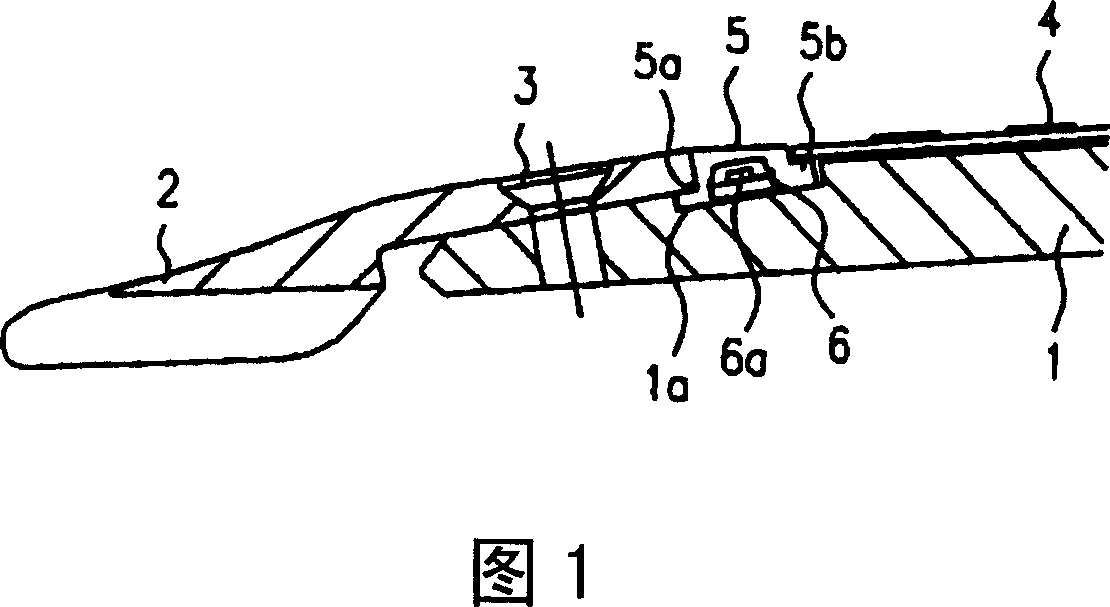
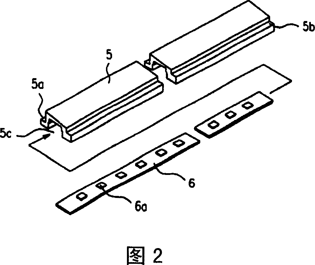
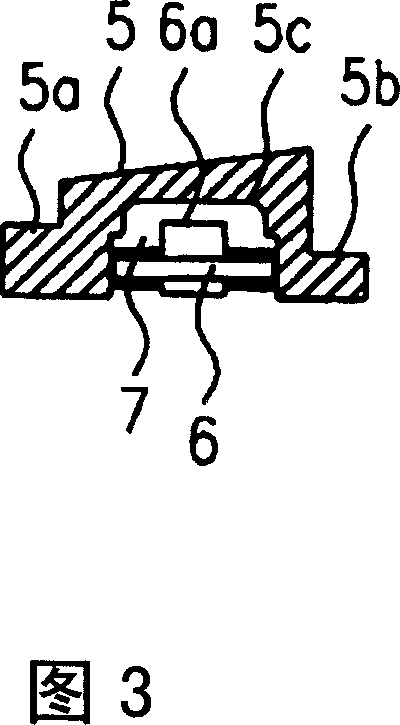
[0017] Fig. 1 is a longitudinal sectional view showing an embodiment of the entrance and exit safety device of the passenger conveying equipment of the present invention, Fig. 2 is a detailed perspective view of the entrance and exit safety device, and Fig. 3 is a longitudinal sectional view of the entrance and exit safety device.

[0018] As shown in Figure 1, the passenger conveyor is provided with a comb plate 1 with an inclined surface installed at the entrance and exit, and a concave recess is provided on the upper surface of the comb plate 1 at a certain distance from the front end. The groove 1a is provided in a spanning manner between two skirt guard plates (not shown) located on both sides of the step. The comb plate 2 is provided on the step side of the groove 1a on the upper s...


PUM


Abstract

A passageway safety device provided convenient passenger transferring equipment, capable of improving anti-drip tile effect and ensuring sufficient intensity, has a belt-shaped covering component made of hard transparent resin and a plaque for mounting LED element, embedded in the rabbet of the belt-shaped covering component, in which, the belt-shaped covering component made of hard transparent resin is provided on the upper surface of the comb plate, and locating between the comb flake and the decorating plate, in which, the comb flake is meshed with the reeding formed on the step by non-contacting state, the decorating plate is provided extending along the buildings flooring direction, the belt-shaped covering component made of hard transparent resin has approximately U-shaped profile, two ends of which are provided with cuts, the plaque is embedded in the rabbet of the belt-shaped covering component, under this state, the space portion between the belt-shaped covering component and the plaque is filled with transparent resin, while the other one cut of the belt-shaped covering component is jointed between the comb plate and the decorating plate to fix the belt-shaped covering component.

Description

Technical field [0001] The invention relates to an entrance and exit safety device of a passenger conveying equipment that can enable passengers to safely enter and exit at the entrance and exit. Background technique [0002] As a prior art, there has been disclosed a technique of alerting passengers using a passenger conveying device that they have approached the entrance and exit in the form of light. For example, in the technique disclosed in Patent Document 1 Japanese Patent Laid-Open No. 2005-29290, A hollow and elongated rigid transparent resin tube is provided on the comb plate at the entrance and exit, and an illuminating body is provided in the rigid transparent resin tube (for example, refer to Patent Document 1). [0003] In addition, for example, Japanese Patent Application Laid-Open No. 59-212380 of Patent Document 2 discloses a technique that divides a comb plate provided at an entrance into a step side comb plate and an entrance floor side comb. At the same time, a...

Claims


Application Information

Patent Timeline
IPC IPC(8): B66B29/00
Inventor 高桥哲也堀江宣孝小室秀秋
Owner HITACHI LTD
Why Eureka
Try Eureka