
Turbojet pylon for aircraft

A technology for turbine engines and suspension rods, which can be used in aircraft parts, aircraft power plants, power plant construction, etc., and can solve problems such as jet turbine engine power loss

Inactive Publication Date: 2007-07-04
AIRBUS OPERATIONS (SAS)
View PDF0 Cites 10 Cited by
  • Summary
  • Abstract
  • Description
  • Claims
  • Application Information

AI Technical Summary

Problems solved by technology

[0010] Thus in the above case where a box-shaped suspension rod of large size is placed close to the central casing of the jet turbine engine, the suspension rod therefore necessarily leads to a large disturbance of the second flow discharged from the blowing annular channel, thereby directly Expressed as a loss of jet turbine engine power in terms of frontal drag

Method used


Image

  • Turbojet pylon for aircraft
  • Turbojet pylon for aircraft
  • Turbojet pylon for aircraft

Examples


Embodiment Construction

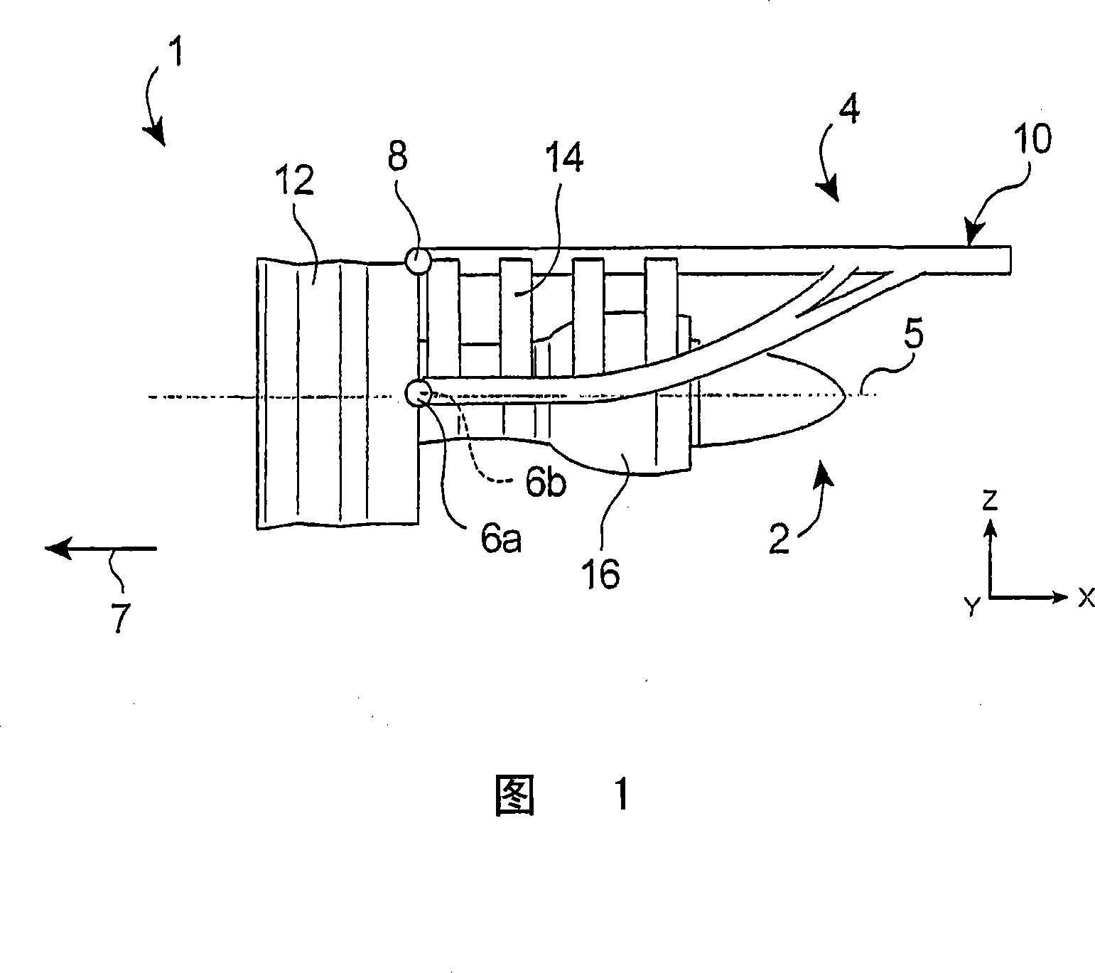
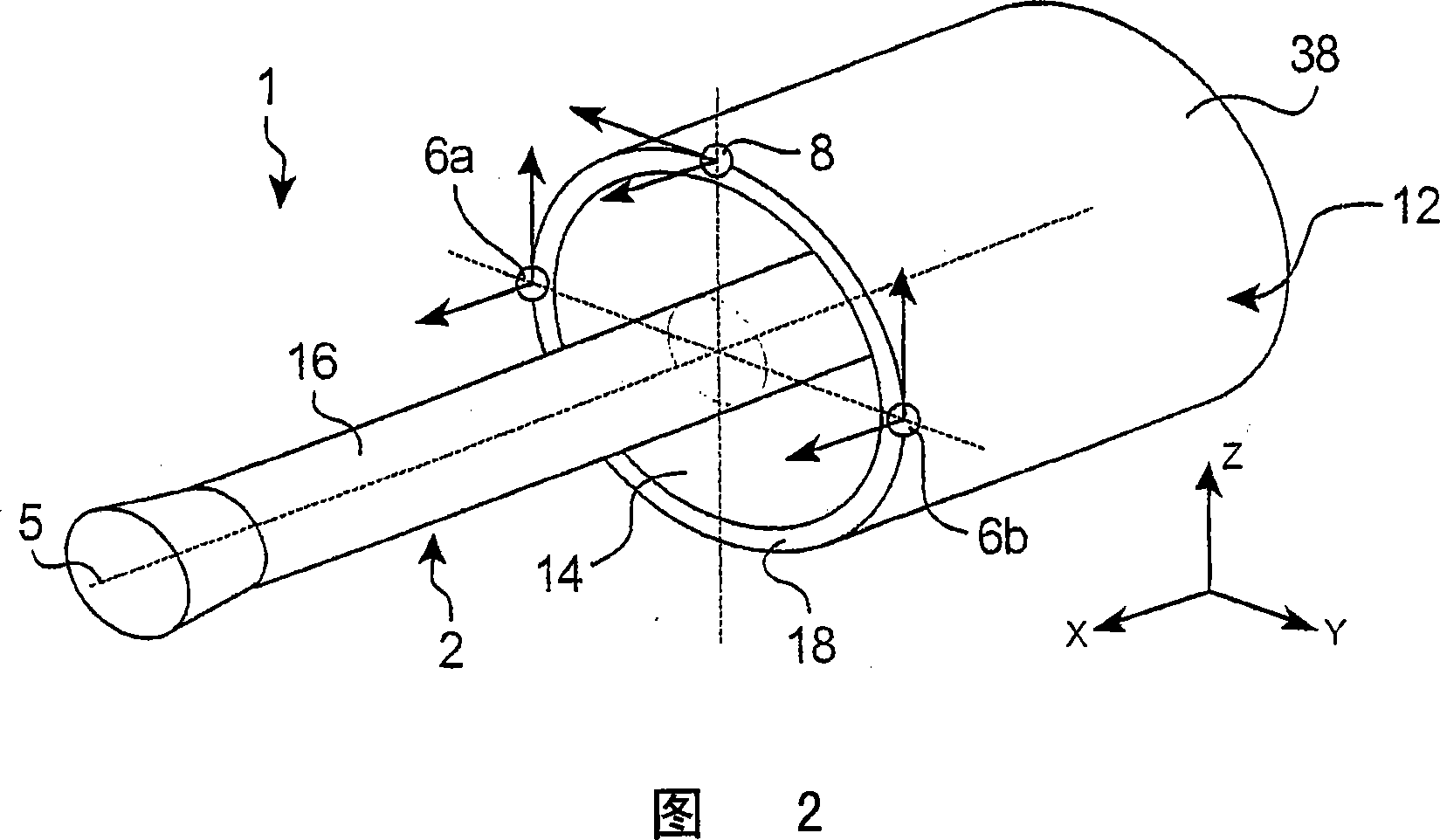
[0044] Referring to Figure 1 , there can be seen an engine assembly 1 for an aircraft, intended to be fixed under a wing (not shown) of the aircraft, comprising a suspension rod 4 according to a preferred embodiment of the invention.

[0045] In general, the engine assembly 1 comprises: a turbine engine 2 and a suspension rod 4 equipped with: a plurality of connecting parts 6a, 6b, 8 and carrying said connecting parts 6a, 6b, 8 (the connecting part 6b is placed on The rigid structure 10 of the connector 6a in FIG. 1 is concealed). By way of example, noting that the assembly 1 is intended to be surrounded by a cockpit (not shown), the suspension rod 4 comprises other series of connections (not shown), allowing to ensure that the assembly 1 is suspended on the wing of the aircraft under.

[0046] Throughout the following description, X designates, by convention, the longitudinal direction of the suspension rod 4 similar to the longitudinal direction of the turbine engine 2 , wh...


PUM


Abstract

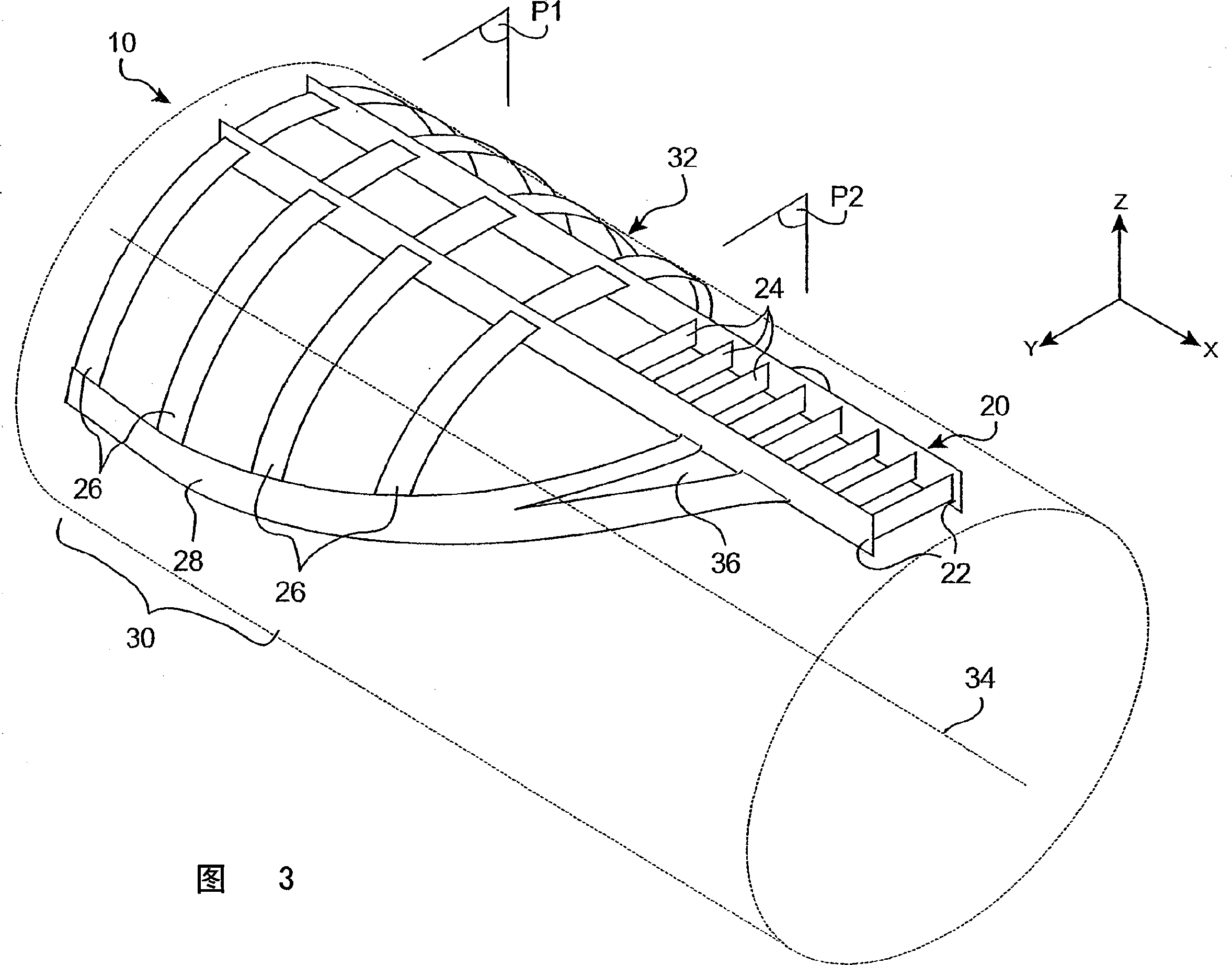
The invention relates to a turbojet pylon for an aircraft, comprising a rigid structure (10) which is equipped with a plurality of half-rings (30) that are arranged such as to define part of an essentially-cylindrical imaginary surface (32) with a circular cross-section. The aforementioned half-rings include two lateral thrust-bearing half-rings (28) which are disposed on either side of a central casing (20). Each of said two lateral half-rings (28) is solidly connected to (i) each half-ring taking the form of an annular segment (26) that is centred on the longitudinal axis of the imaginary surface and (ii) the central casing.

Description

technical field [0001] The present invention generally relates to a suspension rod for a turbine engine of an aircraft, a type of suspension rod for a turbine engine, also known as "EMS" (Engine Mounting Structure), allowing to suspend the turbine engine on the under the wing, or mount the jet turbine engine above the wing. Background technique [0002] Such suspension rods are provided to form the interface between the jet engine and the wing of the aircraft on which the assembly is installed. The suspension rods allow the transmission of the forces generated by the connected engines to the structure of the aircraft and also allow the routing of fuel, electrical systems, hydraulic systems and the air between the engines and the aircraft. [0003] In order to ensure the transmission of said stresses, this suspension bar comprises a rigid structure, usually of the "box" type, ie formed by assembling upper and lower longitudinal beams and lateral plates connected between said...

Claims


Application Information

Patent Timeline
Patent Type & Authority Applications(China)
IPC IPC(8): B64D27/26
CPCB64D27/26B64D2027/264B64D27/402B64D27/40
Inventor L·迪奥昌J·杜兰德
Owner AIRBUS OPERATIONS (SAS)
Learn More