Control device for the optical amplifier

A technology of optical fiber amplifier and control device, which is applied in the direction of optical fiber transmission, electromagnetic wave transmission system, electrical components, etc. It can solve the problems of less SRAM on the chip, affect the production capacity of mass production, and poor processing ability, and achieve increased processing speed and good stability. , The effect of convenient debugging

Inactive Publication Date: 2007-07-11
WUXI TACLINK OPTOELECTRONICS TECH CO LTD
View PDF0 Cites 5 Cited by
  • Summary
  • Abstract
  • Description
  • Claims
  • Application Information

AI Technical Summary

Problems solved by technology

[0005] (1) The circuit control mode is single, either automatic power control APC (Auto Power Control) mode, the product is used in synchronous digital hierarchy (SDH) transmission system, or automatic gain control AGC (AutoGain Control) mode, the product is used in WDM transmission System; the optical power or total gain of the output light cannot be adjusted and set, the product has poor versatility, and cannot be applied to the intelligent transmission network for intelligent control;
[0006] (2) Due to the use of 8bit CPU, the processing ability is poor, the running time is long, and the response to some control signals is relatively slow;
[0007] (3) Since the resources of 8bit CPU are relatively small, such as the flash memory is only 64KB at most, this is limited by only 16 address buses, and the on-chip SRAM is less, so the control program can only complete some basic functions; it cannot realize some intelligent functions control;
[0008] (4) The driving control of the pump is realized by a pure hardware analog circuit. Once the circuit parameters change or the performance of the optical device changes, the total gain or total output optical power will change, and the automatic correction function cannot be realized;
[0009] (5) The production debugging is more complicated. During the production debugging process, it is necessary to repeatedly take out the CPU and place it on the burner for programming and other operations; and once the assembly is completed, the EDFA module needs to be opened to repeat the original debugging steps. Seriously affect the production capacity of mass production and cannot meet the requirements of large-scale production;
[0010] (6) Single-stage linear amplification is used for the detection of input / output optical signals, the detection range is small, and the detection accuracy is very low when the signal is small; this is because the linear amplification detection circuit needs to perform logarithmic operations. The detection accuracy is very low when the signal

Method used


Image

  • Control device for the optical amplifier
  • Control device for the optical amplifier
  • Control device for the optical amplifier

Examples


Embodiment Construction

[0024] The illustrations of the preferred embodiments are not intended to be exhaustive or to limit the invention to the precise forms disclosed. They were chosen and described in order to best explain the principles of the invention and its application and implementation so that others skilled in the art can best utilize the invention.

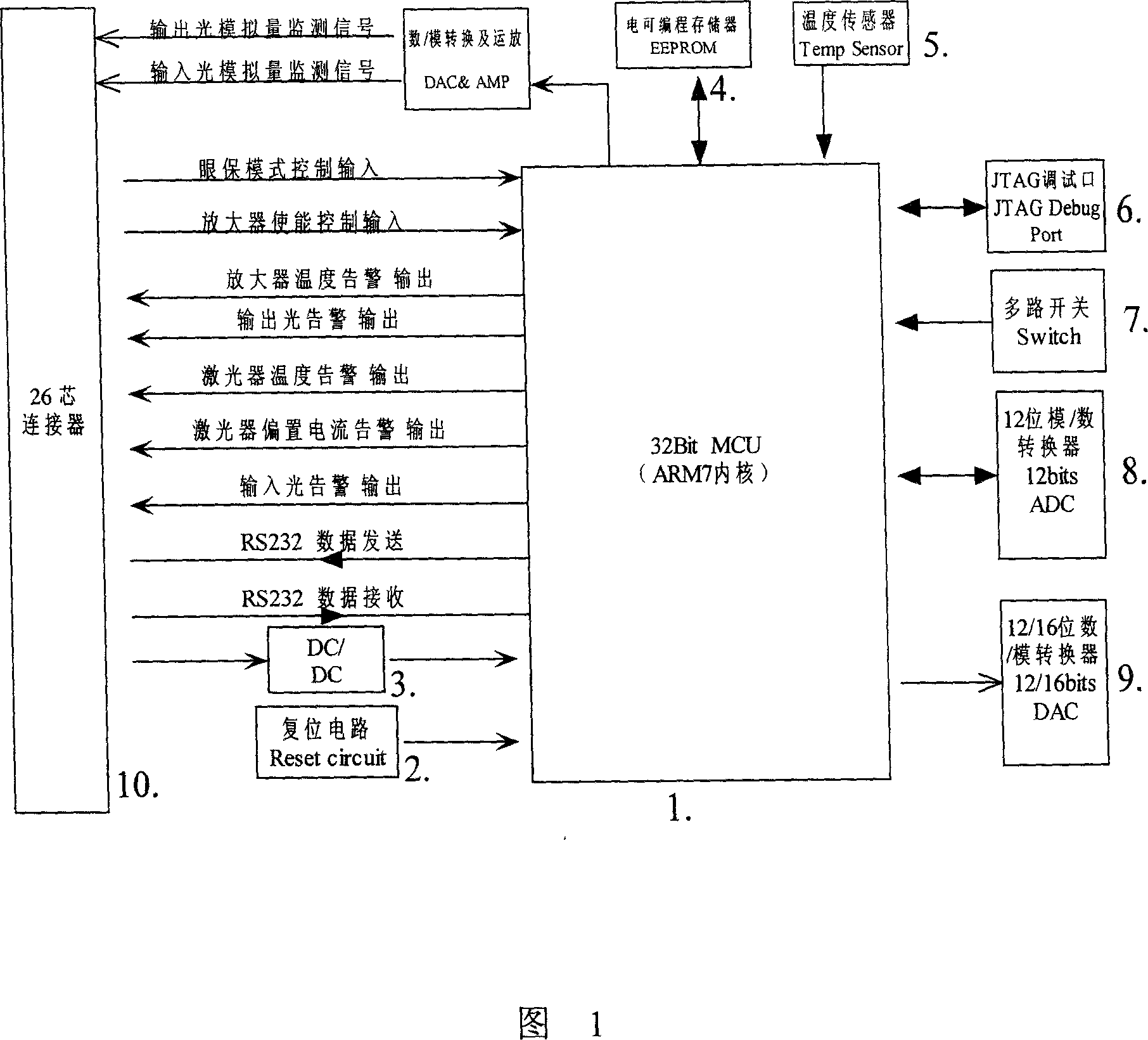
[0025] Figure 1 is a circuit block diagram of a control device for an optical fiber amplifier according to the present invention. The following is a detailed description of each functional circuit marked in Figure 1:

[0026] 1 in Fig. 1 is the microcontroller processor (MCU): LPC2106 of Philips Company is used, which is the ARM7 core, and is the core control part of this design. It adopts 32bit RISC and has strong processing and computing capabilities, which can almost reach 60MIPS, which is better than the original 8Bit The CPU control system is 30 times faster, the running time of the whole system is greatly shortened, and the response to...


PUM


Abstract

This invention relates to one fiber amplifier control device, which comprises connection end, alarm circuit, reset circuit, micro controller, electrical programmable memory and D / A converter to supply circuit of conversion for online testing, ratification, programming interfaces to switch between different modes to collect analogue or digital converter on input, output signals and pump energy with each connected to micro controller for organic control and process.

Description

technical field [0001] The present invention relates to a control device, in particular, to a control device for an optical fiber amplifier. Background technique [0002] Optical fiber amplifier is a revolutionary product in the development of the communication industry. It is widely used in the fields of optical communication, optical network, cable TV and national defense. It is an emerging industry in the 21st century. Fiber amplifiers include doped fiber amplifiers, fiber nonlinear effect amplifiers, etc., which are key components in optical transmission. Erbium-doped fiber amplifiers (Erbium Doped Fiber Amplifier-EDFA) use erbium-doped fiber to directly amplify optical signals, completely rooted In addition to the electronic "bottleneck" formed in the traditional photoelectric repeater; because of its high gain, low noise, high power, wide operating frequency bandwidth, polarization-independent, small channel crosstalk, transparent to transmission code rate and format a...

Claims


Application Information

Patent Timeline
Patent Type & Authority Applications(China)
IPC IPC(8): H04B10/17H04B10/08H04B10/25
Inventor 许建中
Owner WUXI TACLINK OPTOELECTRONICS TECH CO LTD
Why Eureka
Try Eureka