Gas valve

a gas valve and valve body technology, applied in the field of gas valves, can solve the problems of flat contact surface wear, gas valve malfunctions, and relatively quick wear of sealing seats in the form of knife edges

Inactive Publication Date: 2018-06-19
ROBERT BOSCH GMBH
View PDF8 Cites 0 Cited by
  • Summary
  • Abstract
  • Description
  • Claims
  • Application Information

AI Technical Summary

Benefits of technology

[0004]It is the underlying object of the invention to provide a gas valve which is improved as regards its durability.
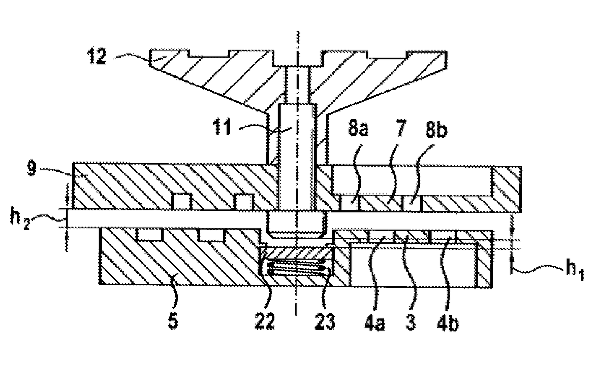
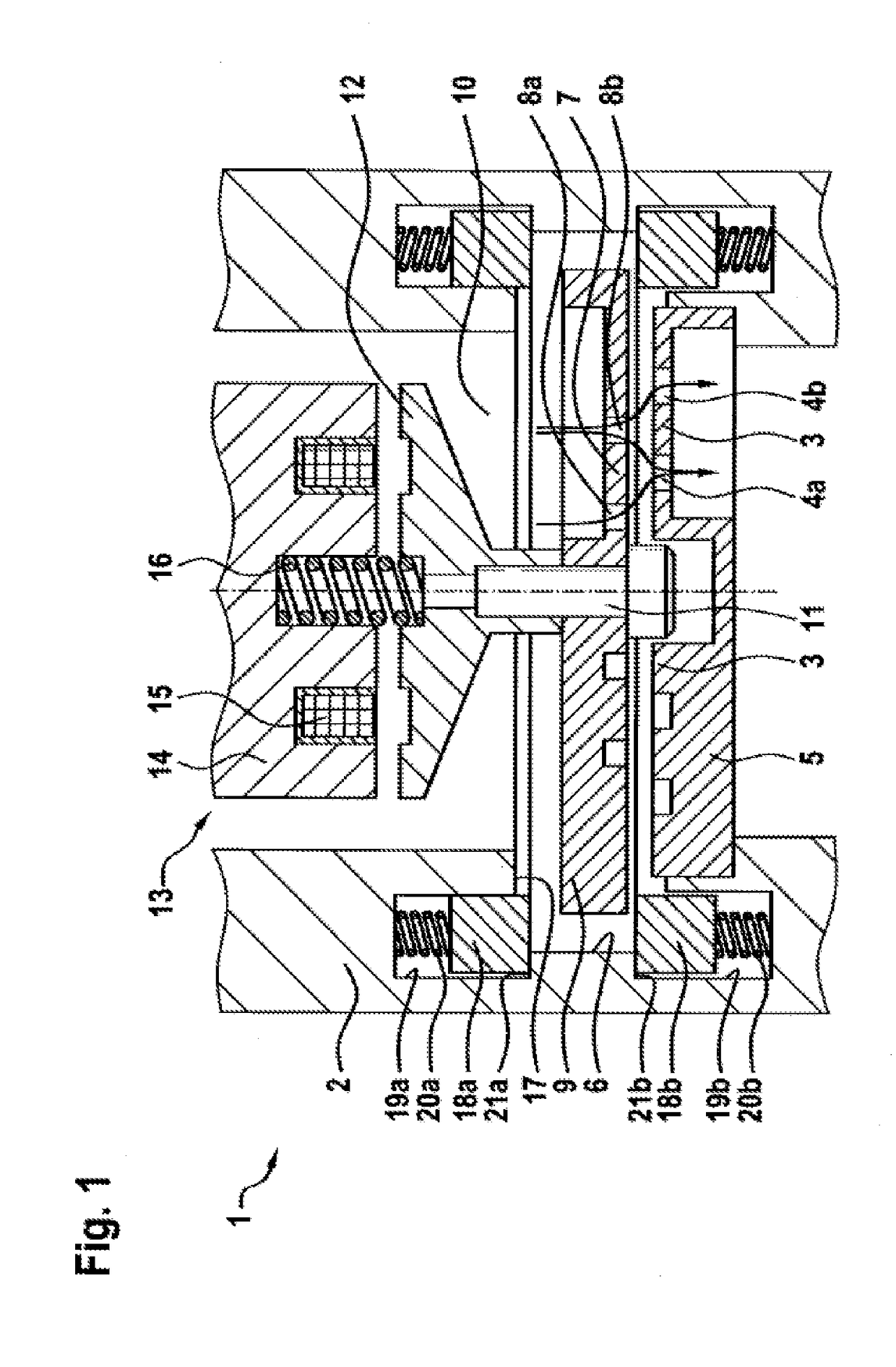
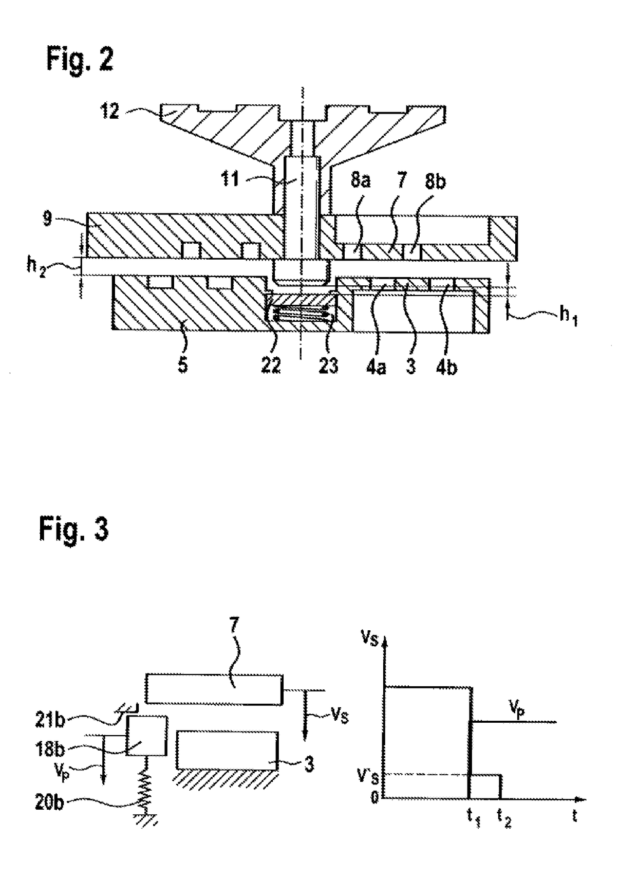
[0005]This object is achieved by virtue of the fact that the gas valve has a damping impact body which reduces the impact speed and / or impact energy of the closing body on the valve seat body and / or on the opening stroke stop. This embodiment is based on the realization that, at the sensitive sealing surface of the valve seat body, the closing body in current gas valves impacts directly on the seat thus formed, without being braked. Complex measures, e.g. special pairs of materials, coatings or a reduction in the mass of the closing body, are necessary to control any possible wear on this sealing surface. During the opening process, the closing body strikes the opening stroke stop in the same way. To maintain a constant stroke and hence a constant opening cross section in relation to the valve seat body over the service life of the gas valve, wear likewise needs to be avoided at this point as well. By virtue of the fact that, according to the invention, an impact body which reduces both the closing speed and the opening speed of the closing body, for example, is provided, any wear that occurs over the service life of the gas valve is prevented or at least significantly reduced in these sensitive regions, thus increasing the durability of the correspondingly designed gas valve.
[0007]In another embodiment of the invention, the impact body is a cylinder or, alternatively, a block arranged centrally in the valve seat body. This embodiment is suitable as a replacement for a corresponding impact body, in the form of an annular body or block for example, arranged on the valve body side but can also be present in addition to such an annular body. If both the annular body, for example, and the central cylinder are present, it is possible to significantly increase the impact area of the closing body and hence to further increase durability. As an alternative, however, the damping rate or the kinetic energy remaining in the closing body after the impact processes can be influenced thereby.
[0010]As a development of the invention, the impact body itself is elastically deformable. This elastic deformability of the impact body can be provided by an appropriate choice of material. By means of this embodiment too, the speed of impact of the closing body on the valve seat body, in particular, is reduced.
[0011]In a development of the invention, the maximum opening stroke of the closing body relative to the valve seat body is greater than the maximum stroke of the closing body relative to the impact body. This embodiment ensures that the closing movement of the closing body is braked only shortly before or immediately before impact on the valve seat body. This ensures that the closing time of the gas valve designed in this way is not changed or not substantially changed, in particular lengthened, as compared with a gas valve without an impact body according to the invention. At the same time, it is possible under some circumstances for a possible lengthening of the closing time to be balanced out by a higher initial closing speed of the closing body. The same applies in reverse to the opening stroke of the closing body.
[0012]In another embodiment of the invention, the impact body includes an alignment function for the closing body relative to the valve seat body. It is thereby possible to compensate for a slight slope in the position of the closing body before impact of the closing body on the valve seat body and thus to ensure more accurate closure of the gas valve.

Problems solved by technology

However, the disadvantage is that the sealing seat in the form of a knife edge can wear relatively quickly owing to the knife-edge design and, as a result, malfunctions in the gas valve thus formed can occur.
However, this flat contact surface is also worn through the action of impacts during operation.

Method used


Image

  • Gas valve
  • Gas valve
  • Gas valve

Examples


Embodiment Construction

[0022]The gas valve 1 shown in FIG. 1 is designed as a gas inlet valve, by means of which a gaseous fuel is fed directly or indirectly to a combustion chamber of an internal combustion engine. In this case, the gas valve can be installed on an intake section of the internal combustion engine and can inject the gaseous fuel centrally into the intake section. However, it is also possible for the gas valve 1 to be installed in an intake branch of the intake section, wherein the intake branch is the intake duct leading to an inlet valve directly adjoining a combustion chamber of the internal combustion engine. In the context of the invention, it is furthermore also possible for the gas valve 1 to be installed in a cylinder head of the internal combustion engine and to be in direct contact on the outlet side with the combustion chamber, bypassing the intake section and the intake duct. By means of the gas valve 1, gaseous fuel is introduced into the combustion chamber, is burnt there wit...


PUM


Abstract

A gas valve 1, in particular a dosing valve for a gaseous medium, having a valve seat body 3, which is arranged on a valve housing 2, and a closing body 7, which can perform a stroke motion relative to the valve seat body 3 and to an opening stroke stop 17 interacting with the valve housing 2. According to the invention, a gas valve 1 is provided which is improved as regards its durability. This is achieved by virtue of the fact that the gas valve 1 has an impact body which reduces the impact speed and / or impact energy of the closing body 7 on the valve seat body 3 and / or on the opening stroke stop 17.

Description

BACKGROUND OF THE INVENTION[0001]The invention relates to a gas valve, in particular a dosing valve for a gaseous medium, having a valve seat body, which is arranged on a valve housing, and a closing body, which can perform a stroke motion relative to the valve seat body and to an opening stroke stop interacting with the valve housing.[0002]A gas valve of this kind is known from DE 10 2009 002 836 A1. This gas valve is a dosing valve for a gaseous medium, which has a valve chamber arranged in a valve housing and having at least two chamber openings, of which a first chamber opening is surrounded in an annular manner by a valve seat, and a closing body, which is arranged in the valve chamber and on which a sealing seat that can be placed on the valve seat and raised from the valve seat is formed. The sealing seat is in the form of a knife edge and thereby ensures leaktight seating upon initial commissioning of the gas valve by means of a sealing impact into the closing body. However,...

Claims


Application Information

Patent Timeline
Patent Type & Authority Patents(United States)
IPC IPC(8): F16K31/06F02M21/02F02M35/10F02M63/00F16K3/02F16K47/04
CPCF02M63/0031F02M21/0239F02M35/10216F02M35/10255F02M63/0077F16K3/0218F16K31/0689F16K47/04Y02T10/32Y02T10/30
Inventor MINIXHOFER, CLAUSMITTER, ROLANDHAINBERGER, MARTIN
Owner ROBERT BOSCH GMBH
Why Eureka
Try Eureka