Optical fiber base material machining method

a technology of optical fiber and base material, which is applied in glass production, glass making apparatus, manufacturing tools, etc., can solve the problems of achieve the effect of increasing the machining time and worsening the surface state of the optical fiber base material

Active Publication Date: 2018-07-03
SHIN ETSU CHEM IND CO LTD
View PDF4 Cites 0 Cited by
  • Summary
  • Abstract
  • Description
  • Claims
  • Application Information

AI Technical Summary

Benefits of technology

[0009]As an outer diameter of the optical fiber base material becomes greater, the drawing to form the spindle shapes, a gas amount necessary for preheating, and the machining time increase. As a result, an adhesion amount of glass microparticles known as a silica cloud that adheres to a region on the surface of the optical fiber base material near the region heated by the flame increases, and this worsens the surface state of the optical fiber base material. Here, a machining method by which the adhesion amount of the silica cloud does not increase even when enlarging the diameter of the optical fiber base material has been desired. In one aspect of the present invention, provided is an optical fiber base material machining method to sever the optical fiber base material after reducing a diameter of the optical fiber base material to a predetermined target outer diameter at a predetermined machining position, and to form spindle-shaped parts at ends of the optical fiber base material, the optical fiber base material machining method comprising: a stage of reducing the outer diameter of the optical fiber base material to a predetermined intermediate outer diameter between the outer diameter before the machining and the target outer diameter at the machining position, a stage of flame polishing the surface of the optical fiber base material with the diameter reduced to the intermediate outer diameter in a region including the machining position, and a stage of further reducing the diameter of the optical fiber base material.

Problems solved by technology

As a result, an adhesion amount of glass microparticles known as a silica cloud that adheres to a region on the surface of the optical fiber base material near the region heated by the flame increases, and this worsens the surface state of the optical fiber base material.

Method used


Image

  • Optical fiber base material machining method
  • Optical fiber base material machining method
  • Optical fiber base material machining method

Examples


first manufacturing example

[0048]Spindle-shaped portions were formed in a plurality of the optical fiber base materials 1 by using a glass lathe that horizontally grips the optical fiber base materials 1 with a hydrogen flame burner, having an oxygen nozzle that discharges oxygen gas as a combustion-assisting gas, as a heating source. The average outer diameter of the optical fiber base materials 1 set horizontally on the glass lathe was ϕ 85 mm.

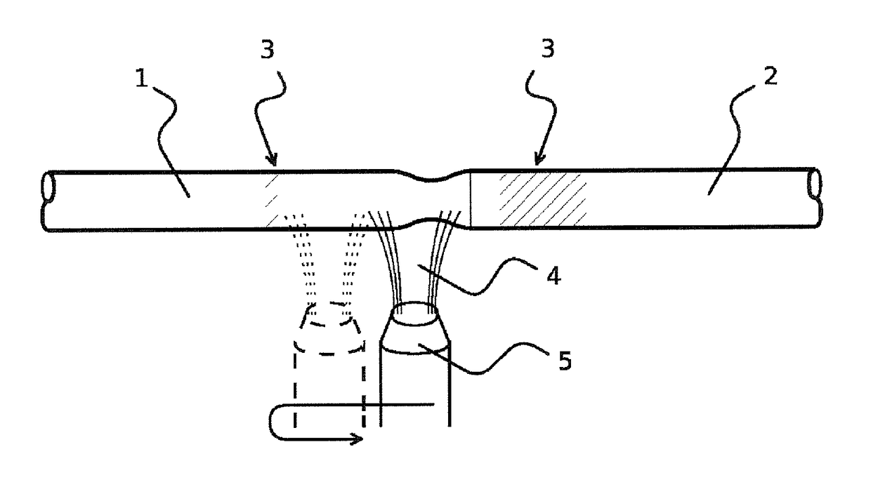
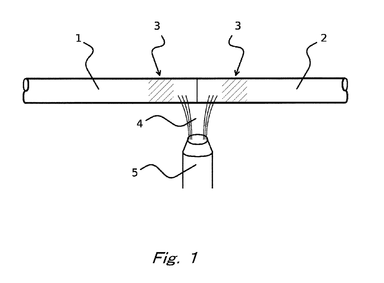
[0049]First, as the preheating, the burner 5 injected and blew the burner flame 4 from the connection portion between the optical fiber base material 1 and the dummy rod 2 toward the start position which was separated by 20 mm from the optical fiber base material 1 side. Accordingly, this position of the optical fiber base material 1 was heated and softened.

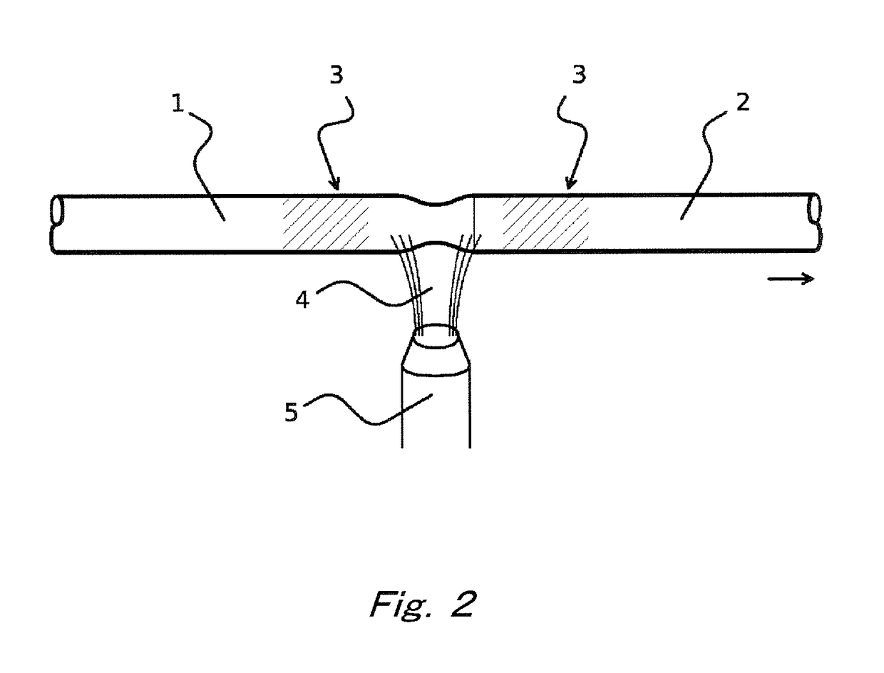
[0050]While the heated portion of the optical fiber base material 1 was in a softened state, the softened portion of the optical fiber base material 1 was elongated by increasing the space of the chuck gripping the...

second manufacturing example

[0054]The drawing to form the spindle-shaped portions was performed on the other 100 optical fiber base materials 1 using the same glass lathe as the first manufacturing example. Here, the average outer diameter of the optical fiber base materials 1 drawn was ϕ 120 mm.

[0055]First, as the preheating, the burner 5 injected and blew the burner flame 4 from the connection portion between the optical fiber base material 1 and the dummy rod 2 toward the start position that is separated by 30 mm from the optical fiber base material 1 side. In this way, this position of the optical fiber base material 1 was heated and softened.

[0056]While the heated portion of the optical fiber base material 1 was in a softened state, the space of the chuck gripping the optical fiber base material 1 and the dummy rod 2 was increased, and the softened portion of the optical fiber base material 1 was elongated. The operation of the chuck was stopped when the minimum diameter of the diameter-reduced portion of...


PUM

PropertyMeasurementUnit
outer diameteraaaaaaaaaa
diameteraaaaaaaaaa
speedaaaaaaaaaa

Abstract

An optical fiber base material machining method for forming spindle-shaped portions at ends of the optical fiber base material by severing the optical fiber base material after reducing an outer diameter of the optical fiber base material to a predetermined target outer diameter at a predetermined machining position, comprising: reducing the outer diameter to a predetermined intermediate outer diameter between the outer diameter before the machining and the target outer diameter at the machining position; flame polishing a surface of the optical fiber base material in a region including the machining position; and further reducing the outer diameter of the optical fiber base material.

Description

[0001]The contents of the following Japanese patent application are incorporated herein by reference:[0002]NO. 2015-046571 filed on Mar. 10, 2015.BACKGROUND[0003]1. Technical Field[0004]The present invention relates to a machining method of an optical fiber base material.[0005]2. Related Art[0006]An optical fiber base material undergoes a primary elongation with heating and elongation and diameter reduction, using an elongation apparatus that includes an electric furnace, and is machined to have a suitable diameter for a drawing machine. Also, spindle shapes suitable for drawing at both ends or one end of the optical fiber base material are formed by the drawing using a glass lathe. Further, the optical fiber base material is hung by the drawing machine via a dummy glass rod fused to one end of the optical fiber base material, and the optical fiber is drawn forth from a thin diameter portion having the spindle shape at the other end of the optical fiber base material.[0007]An optica...

Claims


Application Information

Patent Timeline
Patent Type & Authority Patents(United States)
IPC IPC(8): C03B37/012C03C25/00C03C25/002C03B37/027
CPCC03B37/01251C03B37/02772C03C25/002Y02P40/57C03B2205/47
Inventor FUJII, HIDEKIKOSHIGAI, TAKASHI
Owner SHIN ETSU CHEM IND CO LTD
Why Eureka
Try Eureka