In tank fuel pump mounting arrangement

a technology for fuel pumps and fuel tanks, which is applied in the direction of liquid fuel feeders, machines/engines, and feed systems, etc., can solve the problems of ineffective use of fuel within the fuel tank, prior art cannot maintain the state in which the pump unit abuts the fuel tank, and achieve the effect of increasing the relative positional relationship between the connecting portion and the pump uni

Active Publication Date: 2018-07-03
AISAN IND CO LTD
View PDF17 Cites 6 Cited by
  • Summary
  • Abstract
  • Description
  • Claims
  • Application Information

AI Technical Summary

Benefits of technology

[0007]According to one aspect of the present disclosure, a fuel supply device comprises a cover member which is attached to an opening of a fuel tank as well as a pump unit having a pump, and a connecting portion connecting the cover member and the pump unit. The pump unit is connected so as to be relatively movable with respect to the connecting portion when a connecting shaft which is formed as part of one of the connecting portion or the pump unit, is inserted into a connecting hole which is formed as part of the other of the two. The connecting hole has an elongated hole portion that allows the connecting shaft to be relatively movable in the upward and / or downward directions relative to the connecting hole. An engagement portion is provided at the pump unit abutting an end (e.g. a lower end) of the connecting portion when the fuel supply device is attached to the fuel tank.
[0008]Therefore, through the abutment, the engagement portion provided at the pump unit can always receive a pressing force from the connecting portion when the fuel supply device is mounted to the fuel tank. Further, since the connecting hole is formed as an elongated hole, a movable range of the connecting shaft is larger than that known in conventional art. Thus, through the expanded range, the flexibility of the relative positional relationship between the connecting portion and the pump unit is increased, and the pump unit can be pressed against the fuel tank by the connecting portion. In this manner, the pump unit can be pressed against the fuel tank even when the fuel tank is deformed to be inclined to follow to the deformation of the fuel tank.
[0012]Accordingly, the engagement portion can be pressed by one part of the curved surface of the lower end of the connecting portion when the fuel tank is not deformed, and can be pressed by the other part of the curved surface when the fuel tank is deformed to be inclined. Consequently, through said pressing, the end of the connection portion can press the engagement portion with relatively good followability to the deformation of the fuel tank.

Problems solved by technology

Therefore, it could not maintain a state in which the pump unit abuts the fuel tank.
Particularly, the prior art could not maintain a state in which the pump unit abuts the fuel tank when a tank bottom surface is inclined as the fuel tank was deformed.
As a result, the fuel within the fuel tank could not be used effectively.

Method used


Image

  • In tank fuel pump mounting arrangement
  • In tank fuel pump mounting arrangement
  • In tank fuel pump mounting arrangement

Examples


Embodiment Construction

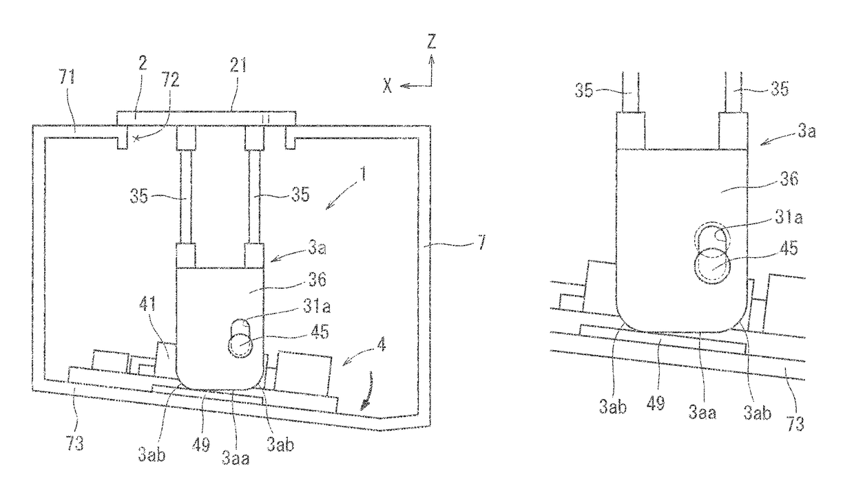
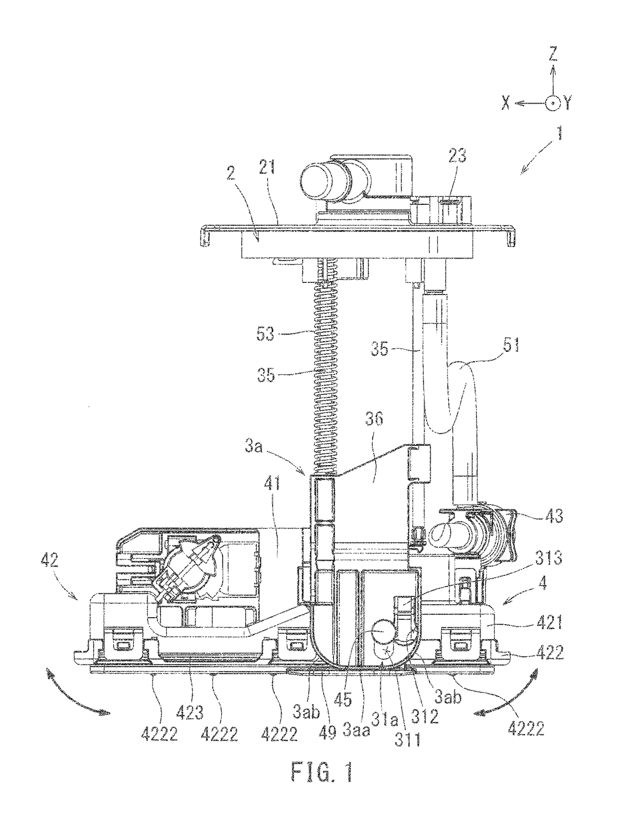
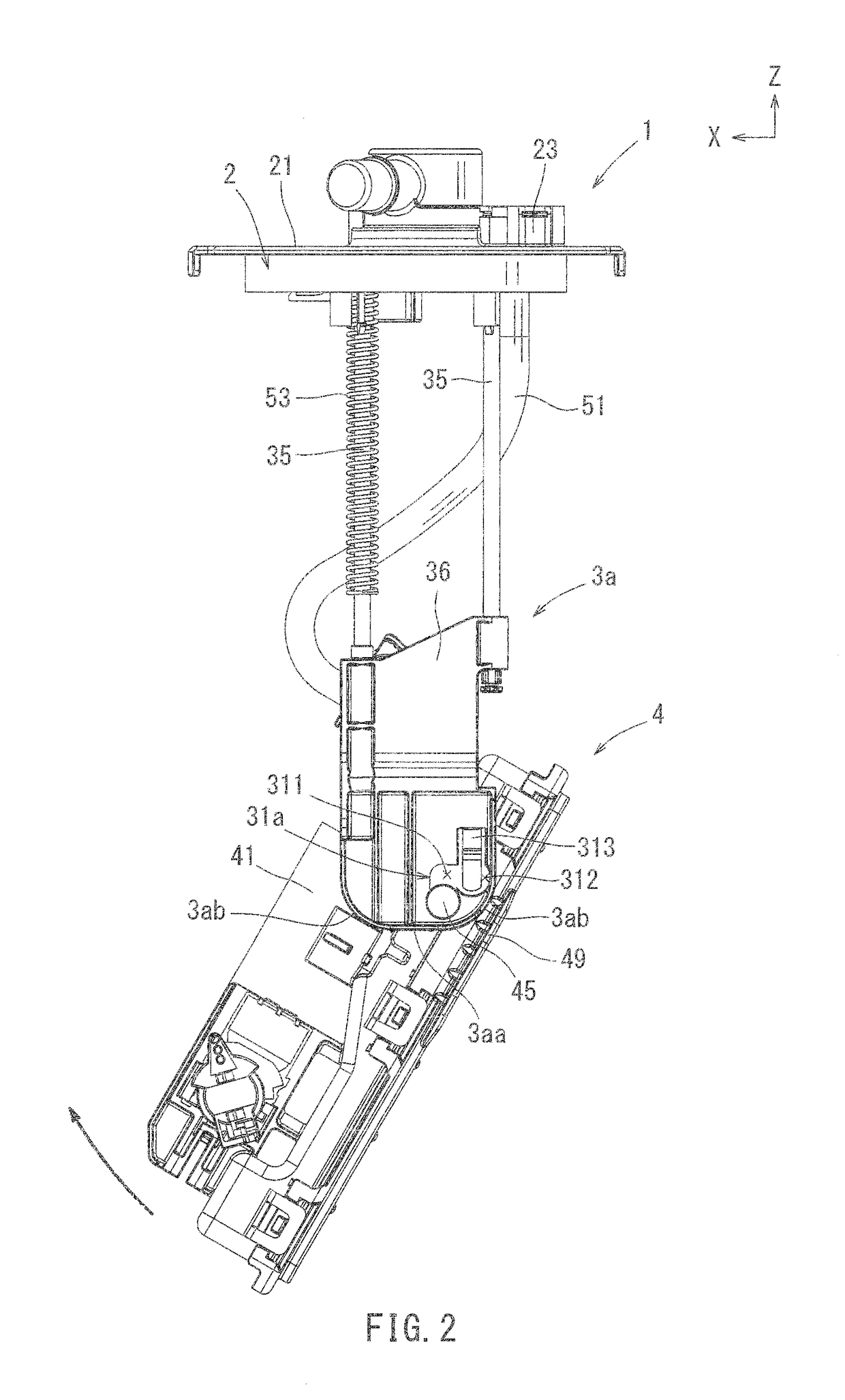
[0020]Hereinafter, one exemplary embodiment of the present disclosure will now be described with reference to the drawings. The forward and backward directions, upward and downward directions as well as the leftward and rightward directions in the present specification are determined such that X is a forward direction, Y is a leftward direction and Z is an upward direction as shown in FIG. 1, where the backwards, leftwards, and downwards directions extend in the negative direction of X, Y, and Z, respectively. A cover member 2 of a fuel supply device 1 is positioned at an upper side and a pump unit 4 is positioned at a lower side of the device. A rotary axis of the pump unit 4 extends in the leftward-to-rightward direction, parallel to the y axis. The forward and backward directions are orthogonal to the leftward and rightward directions as well as the upward and downward directions.

[0021]The fuel supply device 1 according to the present embodiment may be mounted on a vehicle, such ...


PUM


Abstract

A fuel supply device includes a cover member attached to an opening of a fuel tank, a pump unit including a pump, and a connecting portion which connects the cover member and the pump unit. The pump unit is connected so as to be relatively movable with respect to the connecting portion when a connecting shaft which is formed as part of one of the connecting portion or the pump unit, is inserted into the connecting hole formed as part of the other of the two. The connecting hole has an elongated hole portion that allows the connecting shaft to move in the upward and downward directions, and allows the pump unit to be relatively movable with respect to the connecting portion. The pump unit includes an engagement portion abutting a lower terminal end of the connecting portion when the fuel supply device is attached to the fuel tank.

Description

CROSS-REFERENCE TO RELATED APPLICATIONS[0001]The present application is a National Phase entry of, and claims priority to, PCT Application No. PCT / JP2015 / 072658, filed Aug. 10, 2015, which claims priority to Japanese Patent Application No. 2014-171444, filed Aug. 26, 2014, both of which are incorporated by reference herein in their entireties for all purposes.STATEMENT REGARDING FEDERALLY SPONSORED RESEARCH OR DEVELOPMENT[0002]Not applicable.BACKGROUND[0003]The present disclosure relates to a fuel supply device. In particular, the disclosure relates to a fuel supply device for supplying fuel within a fuel tank to an internal combustion engine, wherein the fuel supply device is mounted to a vehicle, e.g. an automobile.[0004]Fuel supply devices mounted to fuel tanks are widely known in the art. It is also widely known that a part of the fuel supply device can be inserted from an opening formed in an upper surface portion of the fuel tank, where the device attaches to said opening when...

Claims


Application Information

Patent Timeline
Patent Type & Authority Patents(United States)
IPC IPC(8): F02M37/10F02M37/00
CPCF02M37/103F02M37/10F02M37/0017F02M37/00
Inventor KONDO, TAKAYUKIYOSHIDA, KOJIFUKUI, TATSUKIHIGASHI, SHINYAKONO, TAKUYAMURAKOSHI, YUICHIYANO, AKIHIRO
Owner AISAN IND CO LTD
Why Eureka
Try Eureka