Water outlet structure

a technology of water outlet and structure, applied in the direction of valve housing, valve operating means/release devices, mechanical equipment, etc., can solve the problems of needing to improve the structure and the inability of people with disabilities to operate the conventional water outlet structur

Active Publication Date: 2018-07-10
YU ZHAN INT CO LTD
View PDF7 Cites 3 Cited by
  • Summary
  • Abstract
  • Description
  • Claims
  • Application Information

AI Technical Summary

Benefits of technology

[0006]One object of the present invention is to solve the aforementioned problems and provide a water outlet structure. A sphere is assembled in a valve room of an inner pipe received in a shell, and the sphere can be rotated by the toggling of the handle. Therefore, when a user cannot lift or release something easily but can toggle something easily, the user can operate the water outlet structure conveniently to allow water flowing out of the shell.
[0007]Another object of the prevent invention is to provide the water outlet structure in which the inner pipe is connected to the shell by a linear connecting head after the sphere and two pads are received in the valve room, rather than integrally formed with the sphere and the two pads. Therefore, prior to assembling the sphere and the two pads in the inner pipe, the structure of the inner pipe can be examined. Under this arrangement, a problem of both of the sphere and the two pads having to be discarded as well as the inner pipe encountered by an inner pipe integrally formed with a sphere and two pads can be prevented.
[0010]In one embodiment, the shaft comprises a seal ring fitting over the inner pipe to prevent from water leakage from a portion of the inner pipe the shaft is assembled to.
[0012]In one embodiment, a seal ring is fitting over the linear connecting head, the seal ring is threaded into the second inner thread along with the first outer thread and placed in the outlet of the inner pipe to prevent from water leakage from a threaded portion between the first outer thread and the second inner thread.

Problems solved by technology

Therefore, handicapped people cannot operate the conventional water outlet structure conveniently, and the structure needs to be improved.

Method used


Image

  • Water outlet structure
  • Water outlet structure
  • Water outlet structure

Examples


Embodiment Construction

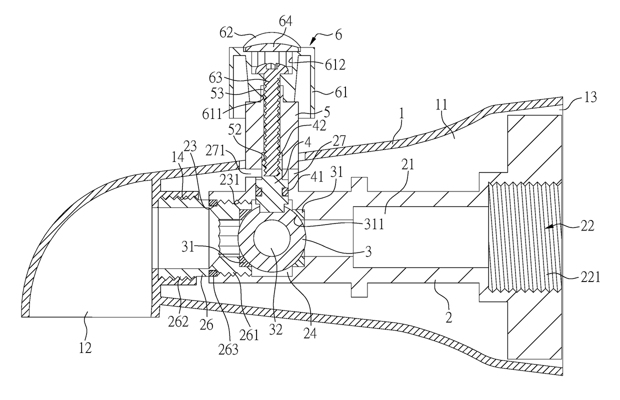
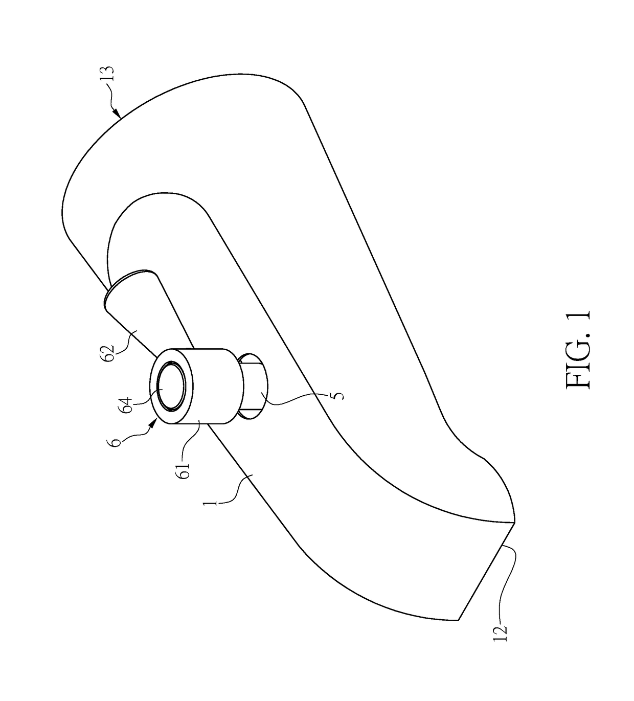
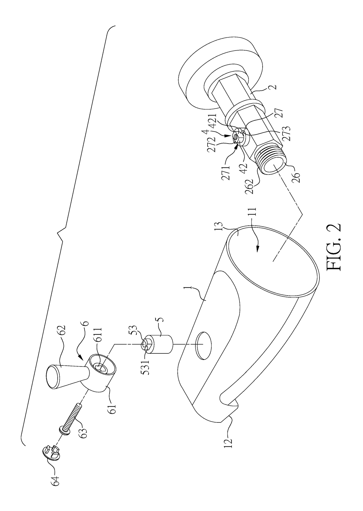
[0025]Please refer to FIGS. 1 to 9, which illustrate a water outlet structure according to embodiments of the present invention. The embodiments are provided for illustrative purposes only and not formed as limitations of the present invention.

[0026]In the embodiment, a water outlet structure is provided. As shown in FIGS. 1 to 3, the water outlet structure comprises a shell 1, an inner pipe 2, a sphere 3, and an operating member. The operating member comprises a shaft 4, a valve bar 5, and a handle 6.

[0027]As shown in FIGS. 1 to 3, the shell 1 is hollowed and has a receiving space 11 therein. One of two ends of the shell 1 has a water outlet end 12, and the other end of the shell 1 distant from the water outlet end 12 has an opening 13. The inner pipe 2 has a channel 21. The channel 21 is defined through the inner pipe 2, and an inlet 22 and an outlet 23 are respectively formed at two ends of the inner pipe 2. A valve room 24 is en route of the channel 21, the end of the inner pipe...


PUM


Abstract

A water outlet structure has an inner pipe connected to a shell. The water outlet structure is connected to a water supply pipe by a locking member. A sphere and two pads are confined in a valve room of the inner pipe. Two ends of a shaft of an operating member are connected to the sphere in the inner pipe and a valve bar. An end of the valve bar extending from the shell is connected to a cap of a handle. A toggle bar of the handle can be toggled to rotate the sphere by only 90 degrees. When the sphere is not rotated, a through hole of the sphere is not in communication with a channel of the inner pipe. When the sphere is gradually rotated and eventually by 90 degrees, the through hole is gradually aligned with the channel and in communication with the channel coaxially.

Description

BACKGROUND OF THE INVENTION[0001]Field of the Invention[0002]The present invention relates to a water outlet structure, in particular to a water outlet structure connectable to a pipe to perform water outflow.[0003]Description of the Prior Art[0004]As shown in FIG. 10, a conventional water outlet structure includes a shell 91 and an inner pipe 92 received in the shell 91. The inner pipe 92 can be connected to a supply pipe 93 for water supply. A pull bar 94 is assembled to a water outlet end 911 of the shell 91. Upon water flows out of the supply pipe 93 and flows through the inner pipe 92, when the pull bar 94 is lifted, water is blocked and not flowing out of the water outlet end 911. While when the pull bar 94 is released, water is unblocked and flowing out of the water outlet end 911.[0005]Whether water can flow out of the water outlet end 911 or not is controlled by the location of the pull bar 94, i.e., whether the pull bar 94 is lifted or released. Even the operation of the p...

Claims


Application Information

Patent Timeline
Patent Type & Authority Patents(United States)
IPC IPC(8): F16K27/06F16K5/06F16K31/60E03C1/04
CPCF16K31/602E03C1/04F16K27/067E03C1/0404F16K5/0642E03C1/0403
Inventor YANG, YA HUI
Owner YU ZHAN INT CO LTD
Why Eureka
Try Eureka