Sensing system and method for analyzing a fluid at an industrial site

a technology of sensing system and fluid, applied in the direction of instruments, measurement devices, scientific instruments, etc., can solve the problems of affecting the quality of fluid samples,

Active Publication Date: 2018-07-10
GE INFRASTRUCTURE TECH INT LLC
View PDF124 Cites 17 Cited by
  • Summary
  • Abstract
  • Description
  • Claims
  • Application Information

AI Technical Summary

Problems solved by technology

Lubricants reduce the friction between two parts that engage each other and may also dissipate heat that is generated by the friction between the two parts.
The sealed interfaces, however, are often exposed to harsh conditions.
For example, gear trains of locomotives are frequently exposed to large differences in temperature, humid environments, dry environments, abrasive dirt or grime, and / or challenging vibratory states.
These conditions may cause a failure in the sealed interface thereby resulting in leakage of the lubricant.
When an insufficient supply of lubricant is available for the gears, the machine may be susceptible to gear train or rolling element bearing damage that results in a locked axle condition.
Both the removal and repair of the locomotive may be time-consuming and costly.
Furthermore, the lost productivity of the locomotive is also costly.
For example, lubricants in a reservoir can become contaminated by water, metallic particles, and non-metallic particles.
Contaminated fluids may lead to damaged parts or a decreased performance of the machine.
In addition, the lubricant may age due to repetitive thermal and viscous cycles resulting in the loss of fluid properties such as viscosity.
These methods may not be practical and / or may have limited capabilities.
For example, due to the configuration of some machines, it may be difficult to visually inspect the fluid.
Also, hardwired sensors may not be suitable for machines that frequently move and / or are exposed to harsh conditions.
When a part of the machine is damaged or otherwise not operating properly, however, the vibrations of the machine may change.
Standard impedance spectroscopy may be limited due to its low sensitivity in reported measurement configurations and prohibitively long acquisition times over the broad frequency range.

Method used


Image

  • Sensing system and method for analyzing a fluid at an industrial site
  • Sensing system and method for analyzing a fluid at an industrial site
  • Sensing system and method for analyzing a fluid at an industrial site

Examples


Embodiment Construction

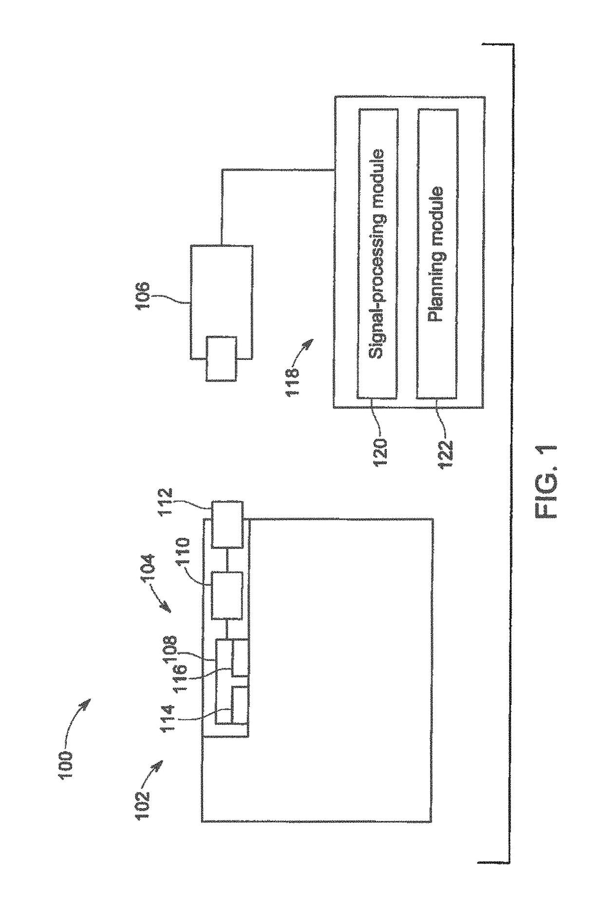
[0104]Embodiments described herein include various systems, assemblies, devices, apparatuses, and methods that may be used in a connection with obtaining one or more measurements of a machine. The measurement(s) may be representative or indicative of an operative condition of the machine. As used herein, an “operative condition of the machine” may refer to an operative condition of the machine as a whole or an operative condition of a component (e.g., element, assembly, or sub-system) of the machine. As used herein, the term “operative condition” relates to a present state or ability of the component and / or a future state or ability. For example, the measurement may indicate that a component is not functioning in a sufficient manner, is damaged, is likely to be damaged if it continues to operate in a designated manner, is not likely to perform appropriately under designated circumstances, and / or is likely to cause damage to other components of the machine.

[0105]As an example with re...


PUM

PropertyMeasurementUnit
frequencyaaaaaaaaaa
frequencyaaaaaaaaaa
frequencyaaaaaaaaaa

Abstract

System includes a sensor operably coupled to a device body. The sensor includes a sensing region and at least one resonant inductor-capacitor-resistor (LCR) circuit. The sensing region is configured to be placed in operational contact with an industrial fluid. The at least one resonant LCR circuit is configured to generate an electrical stimulus that is applied to the industrial fluid via electrodes at the sensing region. The device body includes one or more processors configured to receive an electrical signal from the sensor that is representative of a resonant impedance spectral response of the sensing region in operational contact with the industrial fluid responsive to the electrical stimulus. The one or more processors are further configured to analyze the resonant impedance spectral response and determine both a water concentration in the industrial fluid and an aging level of the industrial fluid based on the resonant impedance spectral response.

Description

CROSS-REFERENCE TO RELATED APPLICATIONS[0001]This application is a continuation-in-part of U.S. patent application Ser. No. 14 / 421,245, filed on 12 Feb. 2015 (the “'245 application”), which claims the benefit of U.S. Provisional Patent Application No. 61 / 692,230, filed on 22 Aug. 2012 (the “'230 application”).[0002]This application also is a continuation-in-part of U.S. patent application Ser. No. 14 / 585,690, filed on 30 Dec. 2014 (the “'690 application”), which claims priority to U.S. Provisional Patent Application No. 61 / 987,853, filed on 2 May 2014 (the “'853 application”). The '690 application is a continuation-in-part of the following applications: U.S. patent application Ser. No. 11 / 560,476, filed on 16 Nov. 2006 (the “'476 application”), U.S. patent application Ser. No. 12 / 325,653, filed on 1 Dec. 2008 (the “'653 application”), U.S. patent application Ser. No. 12 / 824,436, filed on 28 Jun. 2010 (the “'436 application”), U.S. patent application Ser. No. 12 / 827,623, filed on 30 ...

Claims


Application Information

Patent Timeline
Patent Type & Authority Patents(United States)
IPC IPC(8): G01N33/28G01N27/02
CPCG01N27/026G01N33/2888
Inventor POTYRAILO, RADISLAV ALEXANDROVICHWORDEN, BRETTOKAREV, IGOR
Owner GE INFRASTRUCTURE TECH INT LLC
Why Eureka
Try Eureka