Cable pulling assembly having a cable connector and a pulling device

a technology of pulling device and cable connector, which is applied in the direction of optics, fibre mechanical structures, instruments, etc., can solve the problems of reducing the optical performance of fiber optic connectors, inconvenient and complicated first solution in the prior art, and achieves the effect of simple and quick assembly and disassembly

Active Publication Date: 2018-07-10
COMMSCOPE TELECOMM (SHANGHAI) CO LTD
View PDF19 Cites 11 Cited by
  • Summary
  • Abstract
  • Description
  • Claims
  • Application Information

AI Technical Summary

Benefits of technology

[0009]According to an object of the present invention, there is provided a cable pulling assembly comprising a pulling device capable of easily assembled on a connector in the field and simply disassembled from the connector in the field.
[0035]In the above exemplary embodiments of the present invention, the pulling device can be simply and quickly assembled to and disassembled from the housing of the connector in the field.

Problems solved by technology

Thereby, the first solution in the prior art is inconvenient and complicated.
As for the second solution, although it is very simple, a ferrule assembly of the fiber optic connector is directly exposed in the elongated pipe, and the ferrule assembly may be scratched by the pipe wall or contaminated by dirt in the pipe, decreasing the optical performance of the fiber optic connector.

Method used


Image

  • Cable pulling assembly having a cable connector and a pulling device
  • Cable pulling assembly having a cable connector and a pulling device
  • Cable pulling assembly having a cable connector and a pulling device

Examples


second embodiment

[0067]As shown in FIG. 5, in the cable pulling assembly a torsion-proof mechanism is provided, so as to prevent the cable from being twisted and turned during pulling the cable through the pipe by means of the cable pulling assembly.

[0068]As shown in FIG. 5, the torsion-proof mechanism mainly comprises a connection member 203 and a rotation sleeve 204. The connection member 203 is formed with a second connection ear portion2032 at one end thereof and a ball head portion 2031 at the other end thereof. The rotation sleeve 204 is formed with a ball socket 2041 at one end thereof and a connection portion for connecting an elongated pulling element, for example, a metal rope crimped on the connection portion, at the other end thereof. The second connection ear portion 2032 of the connection member 203 is connected to the first connection ear portion 202 of the second body 201. The ball head portion 2031 of the connection member 203 is rotatably engaged in the socket portion 2041 of the ...

third embodiment

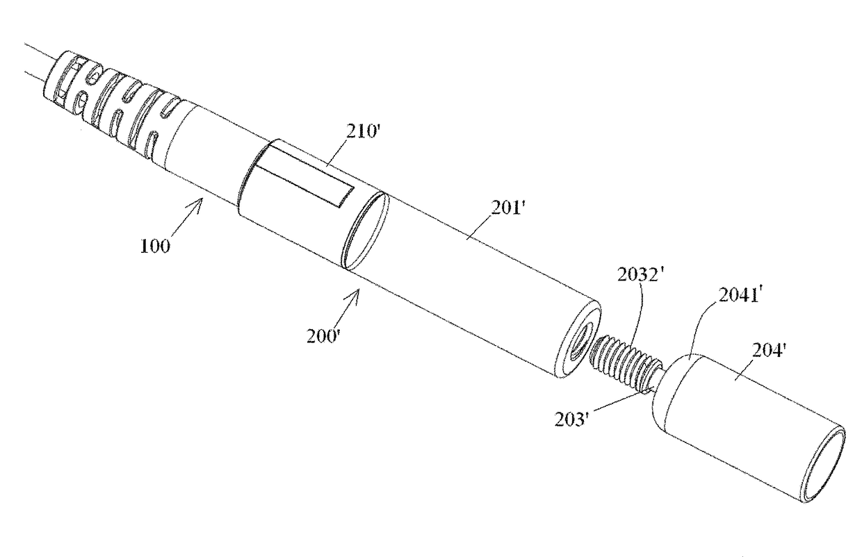
[0071]As shown in FIGS. 6-7, in the cable pulling assembly the pulling device 200′ mainly comprises a first body 210′, a second body 201′, a connection member 203′ and a rotation sleeve204′. The protrusion 221 used as the first engagement portion is formed on an inner wall of the first body 210′. One end of the second body 201′ is removably connected to the first body 210′, and the other end of the second body 201′ is formed with a threaded hole. One end of the connection member 203′ is formed with a threaded post 2032′, and the other end of the connection member 203′ is formed with a ball head portion 2031′. One end of the rotation sleeve 204′ is formed with a socket portion 2041′, and the other end of the rotation sleeve 204′ is adapted be connected to an elongated pulling element (not shown), for example, a rope.

[0072]As shown in FIGS. 6-7, the threaded post 2032′ of the connection member 203′ is screwed into the threaded hole of the second body 201′, and the ball head portion 2...


PUM


Abstract

The present invention discloses a cable pulling assembly, comprising: a connector connected to an end of a cable; and a pulling device connected to a housing of the connector, wherein a first engagement portion is formed on an inner wall of the pulling device, a second engagement portion, adapted to be engaged with the first engagement portion, is formed on an outer wall of the housing of the connector, and when the pulling device is sleeved on the housing of the connector and when the first and second engagement portions are engaged with each other, the pulling device is connected to the housing of the connector. The pulling device can be simply and quickly assembled to and disassembled from the housing of the connector in the field.

Description

CROSS-REFERENCE TO RELATED APPLICATION[0001]This application claims the benefit of Chinese Patent Application No. 201410043292.7 filed on Jan. 29, 2014 in the State Intellectual Property Office of China, the whole disclosure of which is incorporated herein by reference.BACKGROUND OF THE INVENTION[0002]Field of the Invention[0003]The present invention relates to a cable pulling assembly, a method of assembling the cable pulling assembly, and a method of disassembling the cable pulling assembly.[0004]Description of the Related Art[0005]In prior art, when it needs to pull a fiber optic connector through an elongated pipe, there are generally two solutions. In the first solution, a pulling device is sleeved on a housing of the connector, and a rope is tied on the pulling device, the connector is pulled through the elongated pipe by pulling the rope. In the second solution, a rope is directly tied on the housing of the connector, and the connector is pulled through the elongated pipe by ...

Claims


Application Information

Patent Timeline
Patent Type & Authority Patents(United States)
IPC IPC(8): G02B6/44G02B6/38
CPCG02B6/3849G02B6/3887G02B6/3831G02B6/4465G02B6/3821G02B6/4438G02B6/545
Inventor CHENG, XINJUNTONG, ZHAOYANGLIU, LEIQI, LONGZHOU
Owner COMMSCOPE TELECOMM (SHANGHAI) CO LTD
Why Eureka
Try Eureka