Supported radiation protective garment

a radiation protection garment and supported technology, applied in the field of radiation shields, can solve the problems of limited operation radius of operators, difficult to achieve, and require existing catheterization laboratories, c-arms, other x-ray equipment to be retrofitted, etc., and achieve the effect of enhancing radiation protection for operators and less weigh

Inactive Publication Date: 2018-07-10
HEESCH CHRISTIAN MARTIN
View PDF5 Cites 3 Cited by
  • Summary
  • Abstract
  • Description
  • Claims
  • Application Information

AI Technical Summary

Benefits of technology

[0016]A protective coat or apron is provided, consisting of material similar to commercially available protective coats or aprons, although the material may be chosen thicker here, since weight is less of a concern. This will result in enhanced radiation protection for the operator.
[0018]There are numerous advantages to the present invention, as listed below:
[0021]3. Weight not being a significant concern (the operator needs to carry the protective garment's weight only during those short periods when the vertical support members are in their retracted position), a thicker material can be chosen, significantly enhancing the radiation protection offered. Further, an arm extension, used at times by frequent operators to reduce radiation exposure to the left upper arm, which is located in proximity to the X-ray source, and which is not usually covered owing to weight concerns, can now be used without problems.

Problems solved by technology

The disadvantage of this invention is that it requires existing catheterization laboratories, C-arms, and other X-ray equipment to be retrofitted.
Similar to the above Heesch patent, this system requires extensive retrofitting of existing X-ray suites, and the operator's radius of operation is limited by the extension of the rail system.
Further, the majority of invasive procedures involving X-ray exposure require two operators, usually standing side-by-side, which would be difficult to achieve with Rees' proposed ceiling mounted rail system.
The problem with the Beck invention is that it does not allow the operator to maintain sterility, owing to the spatial proximity of the bulky and non-sterile suspension apparatus to the protective apron and the operator's body.
Further, the operators walking and moving space within the rolling apparatus is quite limited.
Tripping and falling accidents seem likely, and may be severe.

Method used


Image

  • Supported radiation protective garment
  • Supported radiation protective garment
  • Supported radiation protective garment

Examples


first embodiment

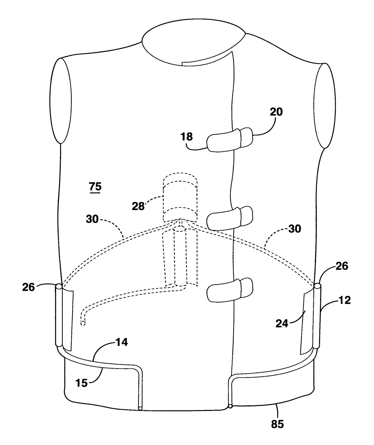
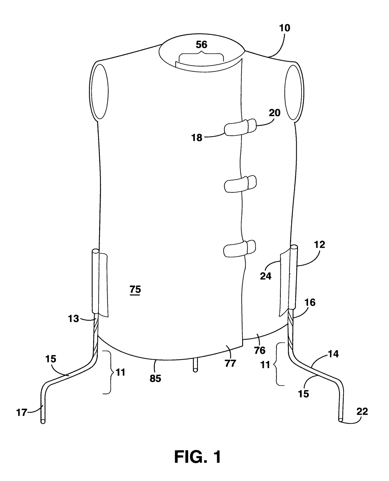
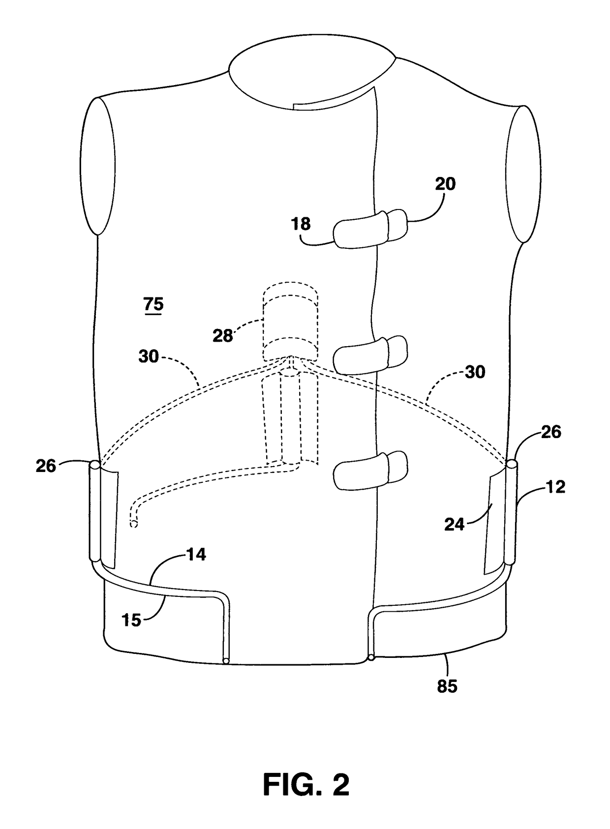
[0068]FIG. 1 shows the present invention, generally labeled 10. The operator dons protective garment 10 in the standard fashion, the front portion shows and area of overlap of the layers of protective garment 10, providing added protection. Standard male (18) and female (20) parts of a buckle closure mechanism are illustrated, a plurality of buckle closure mechanism is suggested. Toward the lower portion of protective garment 10, vertical support means 11 are shown, having an attachment part 24 with which they are firmly attached to the fabric of protective garment 10, a fixed portion 12 and an extending portion 14. Extending portion 14 is divided into an upper vertical part 13, a horizontal part 15, and a distal vertical part 17. At the caudal end of distal vertical part 17 rolling means 22 are provided. A variety of standard rolling or sliding means can be used, including but not confined to a wheel attached to a rotating joint (similar to the wheels of a shopping cart), a rolling...

second embodiment

[0076]FIG. 8 shows the supported radiation protective garment, divided into a ‘protective apron part’46 and a ‘support base part’48. The advantage of this embodiment is its simplicity. This embodiment has fixed portions 12 of vertical support means 11, but lacks extending portions 14 of vertical support means 11. Instead, at the lower end of fixed portions 12 are female connectors 54 of protective apron part 46. Support base 48 consists of semi-circular joint member 50 securely connecting a plurality of extending portions 74 of support base 48, said extending portions 74 having at their upper end male connectors 52 and at their lower end rolling means 22. Protective apron part 46 is donned by the provider in the standard fashion, whereupon the provider performs the standard surgical handwashing procedure (if a sterile procedure is planned), and dons the usual sterile gown. Following this, an assistant positions support base part 48 around the provider, so that provider stands in the...


PUM


Abstract

A supported radiation protective garment is presented that can be worn by a medical provider under a standard surgical gown during procedures that involve the use of radiation. When used by the provider, the protective garment is lifted by vertical support members which can be extended downward and retracted upward. Rolling or sliding means at the lower end of the vertical support members allow the provider to move unhindered while wearing the radiation protective garment. The provider has access to a control mechanism that allows the shifting between retracted and extended positions of the vertical support members without breaking sterility. An alternative embodiment presents an upper apron portion of the protective garment, which can be manually connected by an assistant to a lower rolling base portion. The invention allows the provider to wear a heavy protective garment, offering significantly better radiation protection than standard ‘lead aprons’, while not being burdened by the weight of the garment. Further, the invention allows to maintain sterility at all times, and gives two or more providers, each wearing this protective garment, the option to work and move in close spatial proximity to each other.

Description

CROSS-REFERENCE TO RELATED APPLICATIONS[0001]This is a non provisional patent application of U.S. Provisional Patent Application Ser. No. 62 / 282,788, filed Aug. 12, 2015.[0002]Priority of U.S. Provisional Patent Application Ser. No. 62 / 282,788, filed Aug. 12, 2015, incorporated herein by reference, is hereby claimed.STATEMENT REGARDING FEDERALLY SPONSORED RESEARCH OR DEVELOPMENT[0003]Not applicableREFERENCE TO A “MICROFICHE APPENDIX”[0004]Not applicableBACKGROUND OF THE INVENTION[0005]1. Field of the Invention[0006]The present invention relates, in general, to radiation shields, and, in particular, to radiation protective garments that are worn by doctors, nurses, and other healthcare providers during medical or surgical procedures that involve the use of radiation.[0007]2. General Background of the Invention[0008]Some invasive medical or surgical procedures require the provider to not only wear sterile gowns and gloves, but also protective gowns or aprons to shield the provider fro...

Claims


Application Information

Patent Timeline
Patent Type & Authority Patents(United States)
IPC IPC(8): G21F3/02F16M11/42A41D13/12A41D1/00A61B6/10G21F3/025
CPCG21F3/02A41D13/1209A41D1/005A61B6/107A41D2400/26A61B6/4423
Inventor HEESCH, CHRISTIAN MARTIN
Owner HEESCH CHRISTIAN MARTIN
Why Eureka
Try Eureka