DC-DC converter with overvoltage protection
a dc-dc converter and overvoltage protection technology, which is applied in the direction of dc-dc conversion, power conversion systems, instruments, etc., can solve the problems of surge voltage damage to the fets that constitute the switching circuit and are connected in series, and capacitance ratio becomes out of balance, so as to reduce the cost and prevent the switching element from being damaged
- Summary
- Abstract
- Description
- Claims
- Application Information
AI Technical Summary
Benefits of technology
Problems solved by technology
Method used
Image

Examples
first embodiment
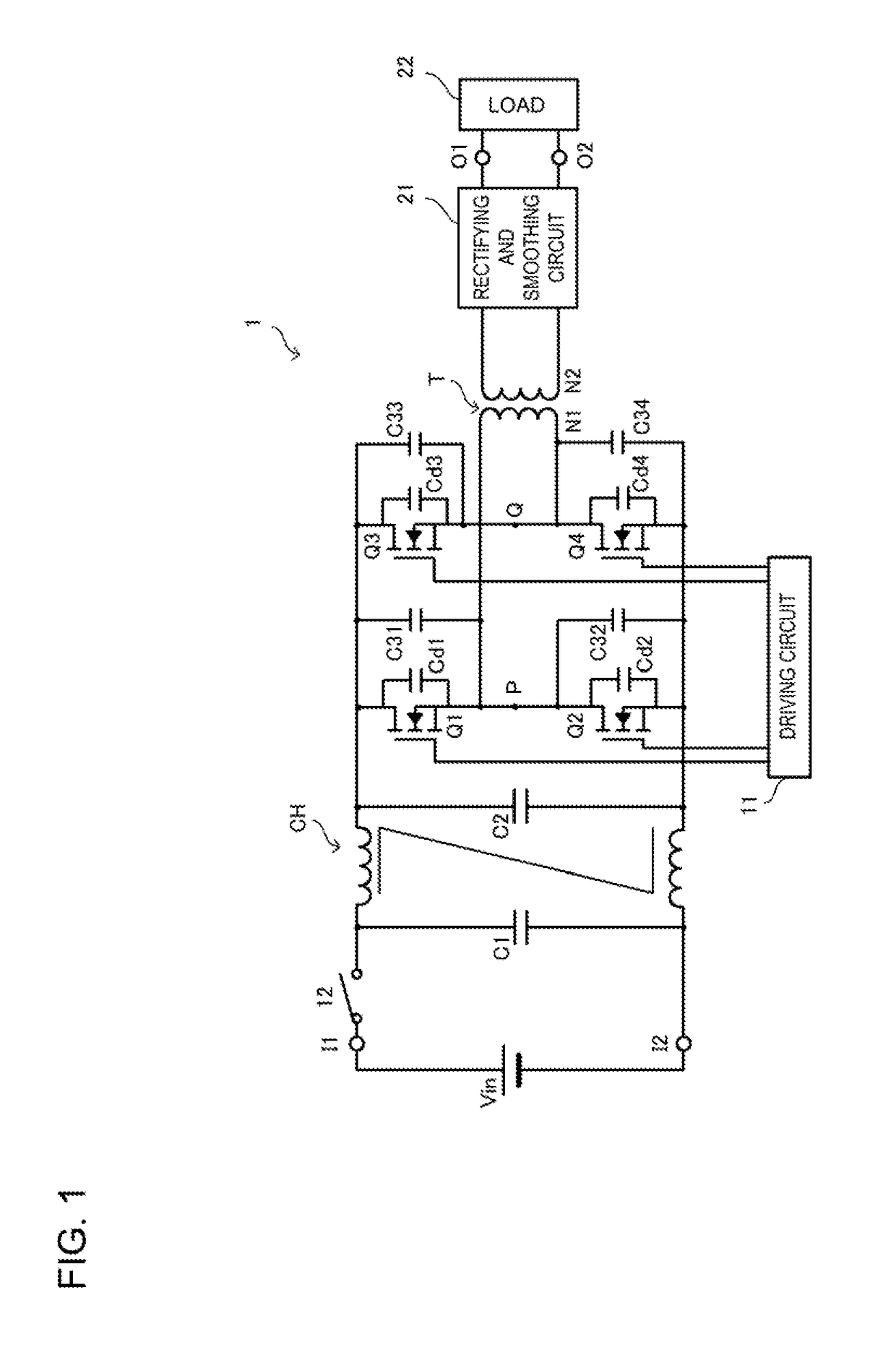
[0028]FIG. 1 is a circuit diagram of a DC-DC converter 1 according to a first embodiment. The DC-DC converter 1 according to the present embodiment. The DC-DC converter 1 includes input terminals I1 and I2 and output terminals O1 and O2. A direct-current power source Vin is connected to the input terminals I1 and I2. A load 22 is connected to the output terminals O1 and O2.
[0029]A switch element 12 and a filter circuit, preferably constituted by a common mode choke coil CH and bypass capacitors C1 and C2, are connected to the direct-current power source Vin as shown. When power is turned on, the switch element 12 is closed and a step-like voltage is applied to the filter circuit.
[0030]A switching circuit (full-bridge circuit) is connected to the output side of the filter circuit. In the switching circuit, a series circuit constituted by semiconductor switches Q1 and Q2 is connected in parallel with a series circuit constituted by semiconductor switches Q3 and Q4. The semiconductor s...
second embodiment
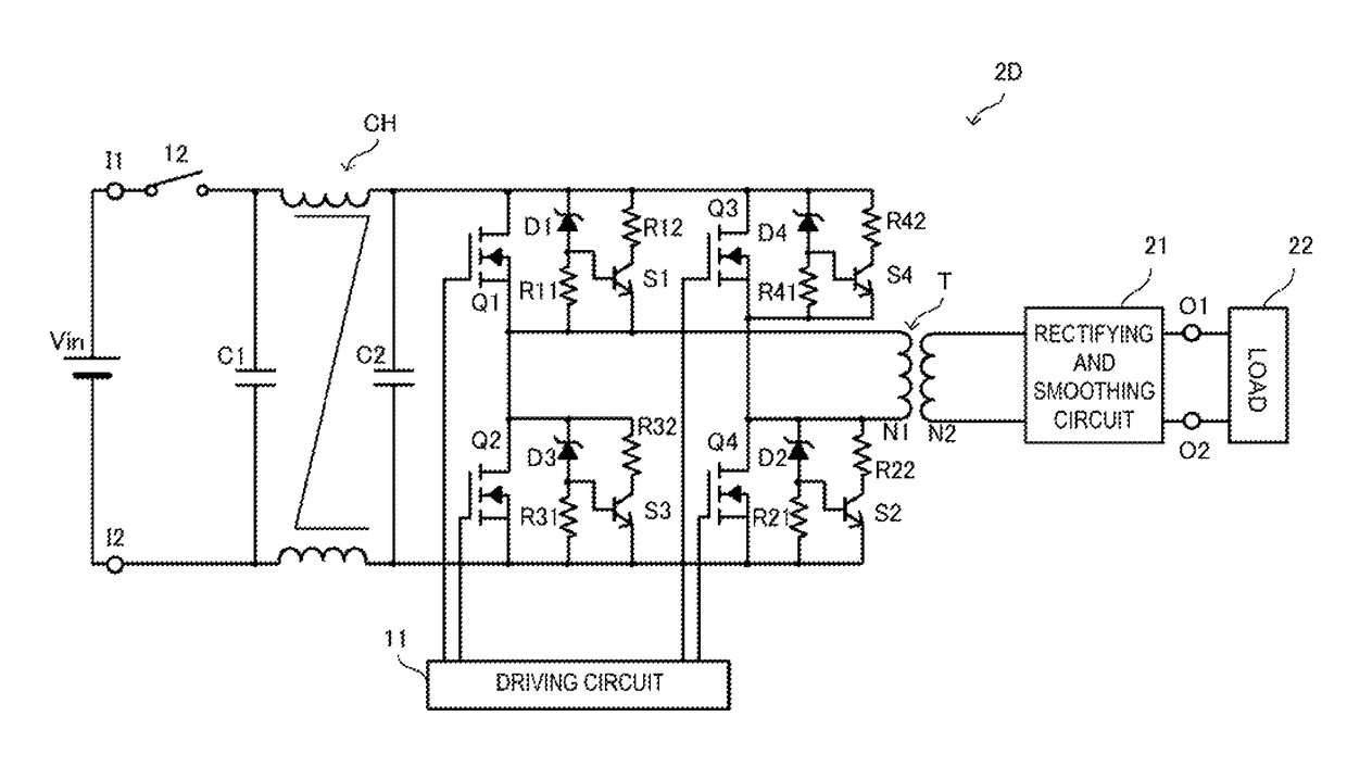
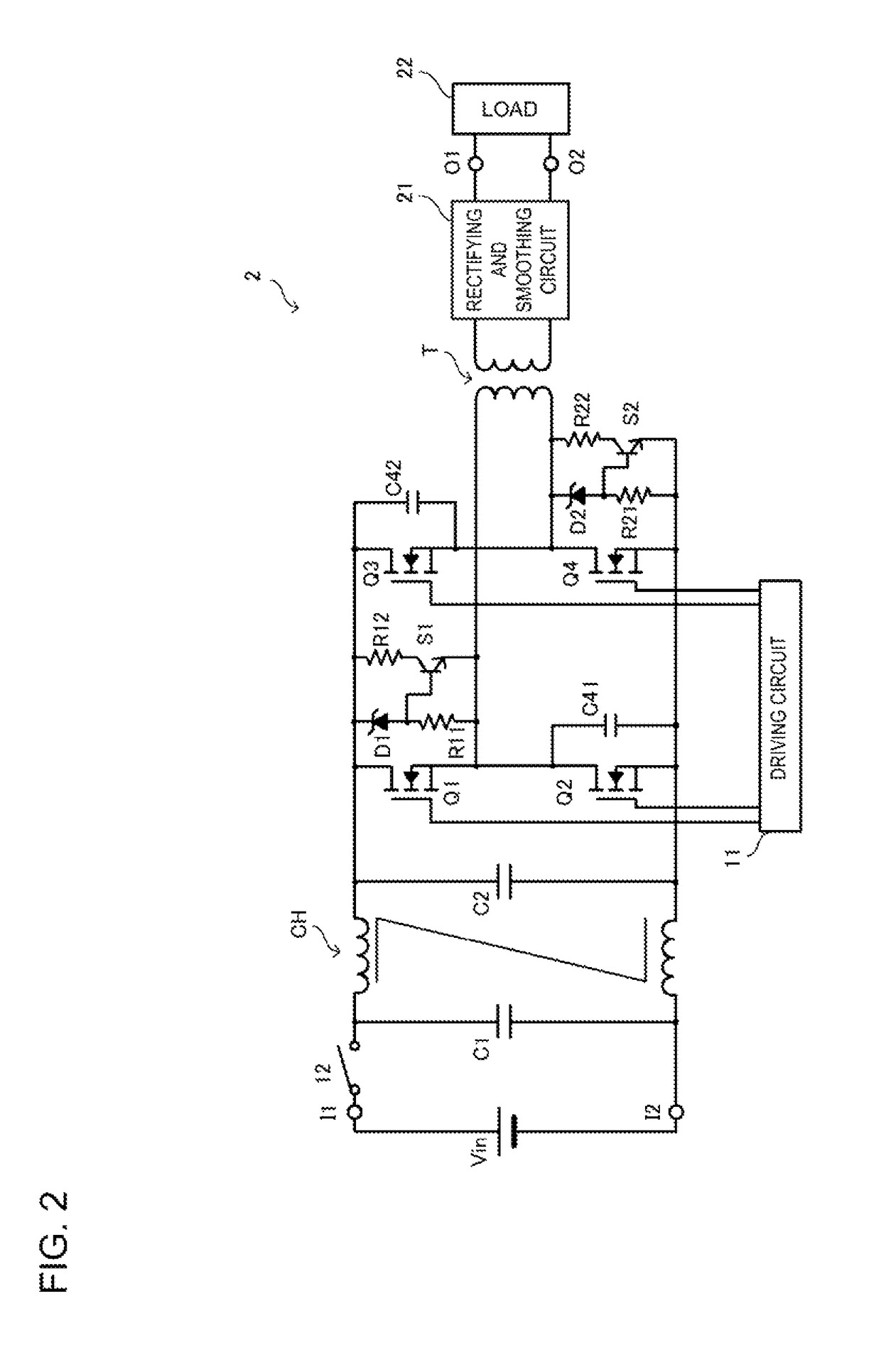
[0041]FIG. 2 is a circuit diagram of a DC-DC converter 2 according to a second embodiment. In FIG. 2, the illustration of parasitic capacitances Cd1 to Cd4 of semiconductor switches Q1 to Q4 is omitted. In this example, a circuit configuration with which the application of an overvoltage to the semiconductor switches Q1 to Q4 is prevented differs from that of the first embodiment. The differences will be described in the following.
[0042]In the DC-DC converter 2, two of the overvoltage protection circuits are overvoltage protection capacitors and two are discharge switch circuits (which are connected in parallel with first and fourth semiconductor switches Q1 and Q4 of a switching circuit). More specifically, a series circuit constituted by a Zener diode D1 and a resistor R11 and a series circuit constituted by a resistor R12 and a switch S1 are connected in parallel with respect to the semiconductor switch Q1. The electronic switch S1 is preferably a transistor, and its base is conn...
third embodiment
[0051]FIG. 7 is a circuit diagram of a DC-DC converter 3 according to a third embodiment. The DC-DC converter 3 according to the present embodiment is a half-bridge circuit in which a series circuit constituted by capacitors C51 and C52 is connected in parallel with a series circuit constituted by semiconductor switches elements Q1 and Q2.
[0052]In the DC-DC converter 3, a discharge switch circuit (acting as an overvoltage protection circuit) is connected in parallel with the semiconductor switch Q1 on the high side. The discharge switch circuit comprises a series circuit constituted by a Zener diode D5 and a resistor R51 and a series circuit constituted by a resistor R52 and an electronic switch S5 which are connected in parallel with the semiconductor switch Q1. In addition, an overvoltage protection capacitor C61 is connected in parallel with the semiconductor switch Q2 on the low side. The capacitor C61 preferably has a capacitance equal to the design value of a parasitic capacit...
PUM
 Abstract
Description
Claims
Application Information
 - R&D
- Intellectual Property
- Life Sciences
- Materials
- Tech Scout
- Unparalleled Data Quality
- Higher Quality Content
- 60% Fewer Hallucinations
Browse by: Latest US Patents, China's latest patents, Technical Efficacy Thesaurus, Application Domain, Technology Topic, Popular Technical Reports.
© 2025 PatSnap. All rights reserved.Legal|Privacy policy|Modern Slavery Act Transparency Statement|Sitemap|About US| Contact US: help@patsnap.com