
Actuation pivot shaft face seal

a technology of actuation pivot shaft and seal, which is applied in the direction of leakage prevention, mechanical equipment, machines/engines, etc., can solve the problems of high turbine output and therefore high charging pressure, and the vtg actuation pivot shaft system is difficult to seal in part, so as to achieve the effect of higher engine efficiency and hence the effect of turbocharger

Inactive Publication Date: 2018-07-17
BORGWARNER INC
View PDF53 Cites 2 Cited by
  • Summary
  • Abstract
  • Description
  • Claims
  • Application Information

AI Technical Summary

Benefits of technology

The patent describes a turbocharger technology that expands the range of flow rates while maintaining high efficiency. This is achieved by adjusting the angle and speed of the exhaust gas flow using guide vanes. The design also reduces wear and damage to the seal ring and other components, resulting in a more robust and reliable turbocharger. The technical effects of this technology are improved performance and durability of turbochargers in practical applications.

Problems solved by technology

When the guide vanes are in a closed position, the high circumferential components of the flow speed and a steep enthalpy gradient lead to a high turbine output and therefore to a high charging pressure.
The VTG actuation pivot shaft system is difficult to seal in part because of the clearance between the shaft and bushings.
As a result, the primary wear interface is between the bushing and disc, since the disc bears against the bushing while the shaft is rotated.
This can be compared to some conventional, rigid face seals which are frequently ineffective for sealing the actuation pivot shaft since the conventional face seal become unseated as the shaft tilts (i.e., to cause axial angular misalignment) or moves axially relative to the bushing.
Were the metal seal ring to instead directly engage the bushing and slide thereagainst while the shaft is rotated, the metal seal ring would likely wear quickly due to the rotational relative motion between the shaft, seal, and bushing.

Method used


Image

  • Actuation pivot shaft face seal
  • Actuation pivot shaft face seal
  • Actuation pivot shaft face seal

Examples


Embodiment Construction

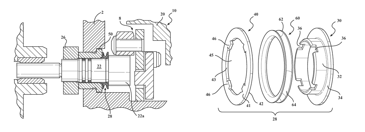
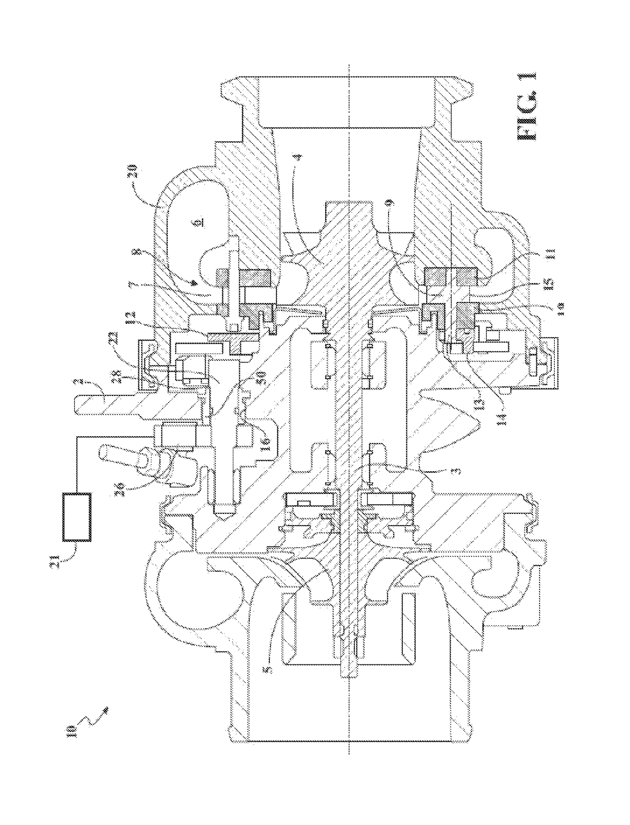
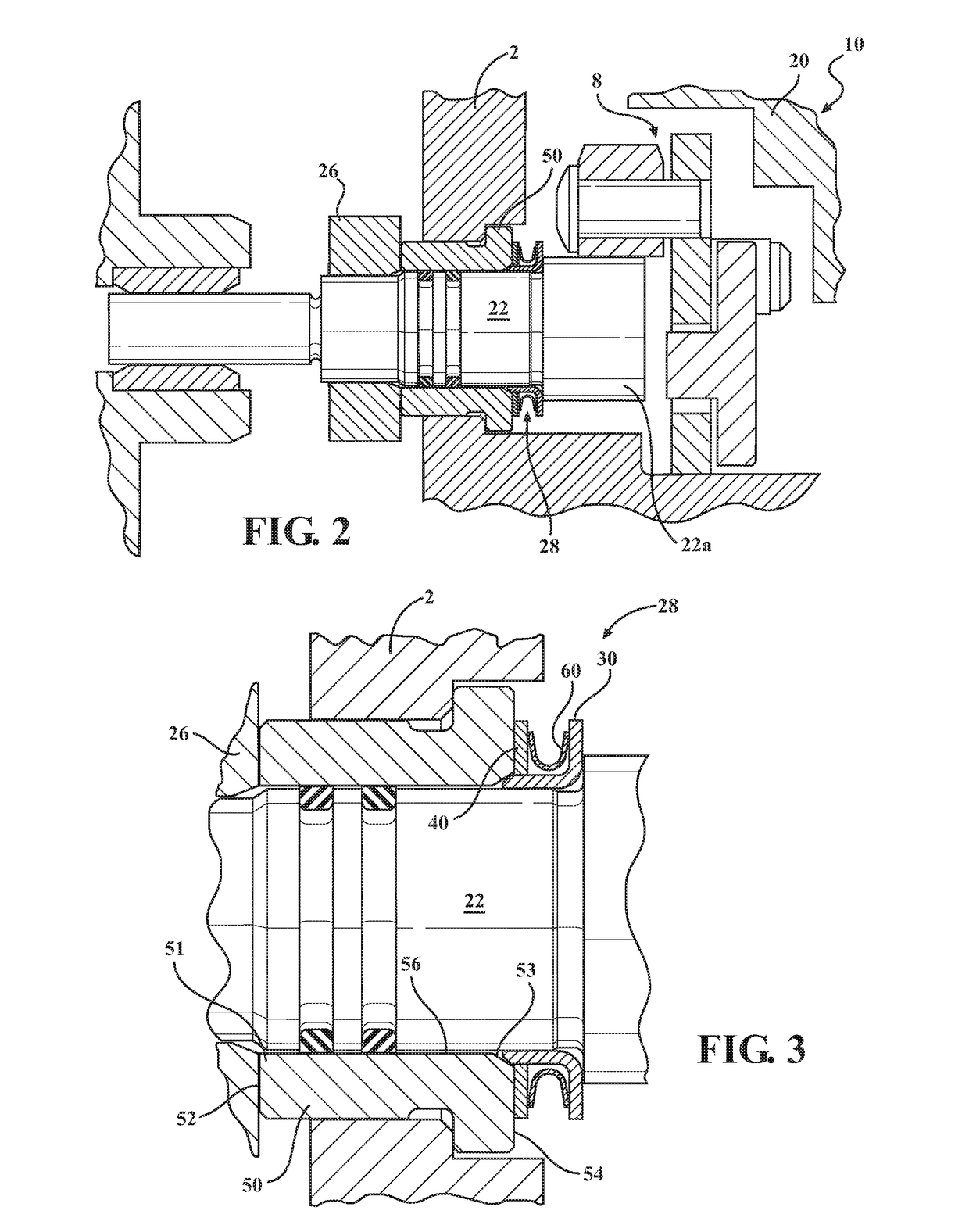
[0042]Referring to FIG. 1, an exhaust-gas turbocharger 10 includes a housing consisting of a bearing housing 2 and turbine housing 20 with a pivoting main shaft 3 rotatably supported in the bearing housing 2. A compressor wheel 5 is carried on one end of the shaft 3, and a turbine wheel 4 is fixed to its other end and is disposed within a chamber defined by the housing (e.g., by one or more of the turbine housing 20 and bearing housing 2). The compressor wheel 5 is rotatably driven via the shaft 3 by the turbine wheel 4. Within the turbine housing 20, on the side of the turbine wheel 4, a volute 6 is formed which, in radial direction, evolves into a throat 7. A VTG assembly 8 including adjustable guide vanes 9 is located inside the throat 7.

[0043]The guide vanes 9 are pivotably supported between an upper vane ring 19 and lower vane ring 11, which are spaced apart by spacers 15. The guide vanes 9 are adjustable through an actuator 21 (depicted schematically) which actuates an adjustm...


PUM


Abstract

A Variable Turbine Geometry (VTG) turbine turbocharger comprises a turbine wheel in a housing, and a compressor wheel coupled to the turbine wheel with a main shaft. The turbocharger additionally includes a VTG assembly in the housing, an actuator outside the housing, and an actuation pivot shaft that extends through an opening of the housing and connects the VTG assembly to the actuator. A face seal assembly seals the opening, and includes an inner ring member rotationally fixed on the pivot shaft, a disc member, and a spring seal. The disc member includes a first face that forms a seal with a surface of the housing, and is rotationally fixed to, while being movable axially relative to, the inner ring member. The spring seal seals the inner ring member and the disc member, and applies a seating force against the disc member.

Description

CROSS-REFERENCE TO RELATED APPLICATION(S)[0001]This application is a continuation-in-part of International Patent Application No. PCT / US2014 / 061444, filed Oct. 21, 2014, which claims priority to and all benefits of U.S. Provisional Application No. 61 / 894,640, filed on Oct. 23, 2013, and entitled “Actuation Pivot Shaft Face Seal With U Seal,” the entire disclosures of which are incorporated herein by reference.BACKGROUND[0002]Field of the Disclosure[0003]This disclosure relates to sealing components in conjunction with an actuation pivot shaft for turbochargers with Variable Turbine Geometry (VTG). More particularly, this disclosure relates to forming a seal with a seal ring between a disc and an inner ring being fit onto the actuation pivot shaft.[0004]Description of Related Art[0005]Advantages of turbocharging include increased power output, lower fuel consumption, and reduced pollutant emissions. The turbocharging of engines is no longer primarily seen from a high-power performanc...

Claims


Application Information

Patent Timeline
Patent Type & Authority Patents(United States)
IPC IPC(8): F02D23/00F02B37/24F02B39/00F02C6/12F02C7/28F16J15/34F01D11/00F16J15/36
CPCF01D11/003F01D11/00F01D11/006F02B37/24F02B39/00F02C7/28F16J15/3452F16J15/3464F02C6/12Y02T10/144F05D2220/40F05D2240/55Y02T10/12
Inventor KENNEDY, DONALD M.
Owner BORGWARNER INC
Learn More