
Adjustment ring damper

a technology of adjustment ring and damper, which is applied in the direction of combustion engines, machines/engines, engine fuctions, etc., can solve the problems of high turbine output, high charging pressure, and acceleration of the wear of the adjustment ring surface, so as to reduce the relative motion between components and reduce the tilting and binding of the adjustment ring during operation.

Active Publication Date: 2019-08-20
BORGWARNER INC
View PDF8 Cites 1 Cited by
  • Summary
  • Abstract
  • Description
  • Claims
  • Application Information

AI Technical Summary

Benefits of technology

This disclosure is about a new type of turbocharger that adjusts its turbine flow to match engine operating points, allowing for better efficiency. The new feature is a retention clip that reduces movement between the various components in the turbocharger, which can help prevent wear and tear. The retention clips also help keep the adjustment ring in place during operation. Overall, this new design allows for better performance and durability of the turbocharger.

Problems solved by technology

When the guide vanes are in a closed position, the high circumferential components of the flow speed and a steep enthalpy gradient lead to a high turbine output and therefore to a high charging pressure.
In some applications, a turbocharger is subjected to vibrational loading that may accelerate the wear of the adjustment ring surface where it contacts the vane lever ramparts.
The clearances allow relative motion between the ring and the surrounding components, which may accelerate wear of the components.
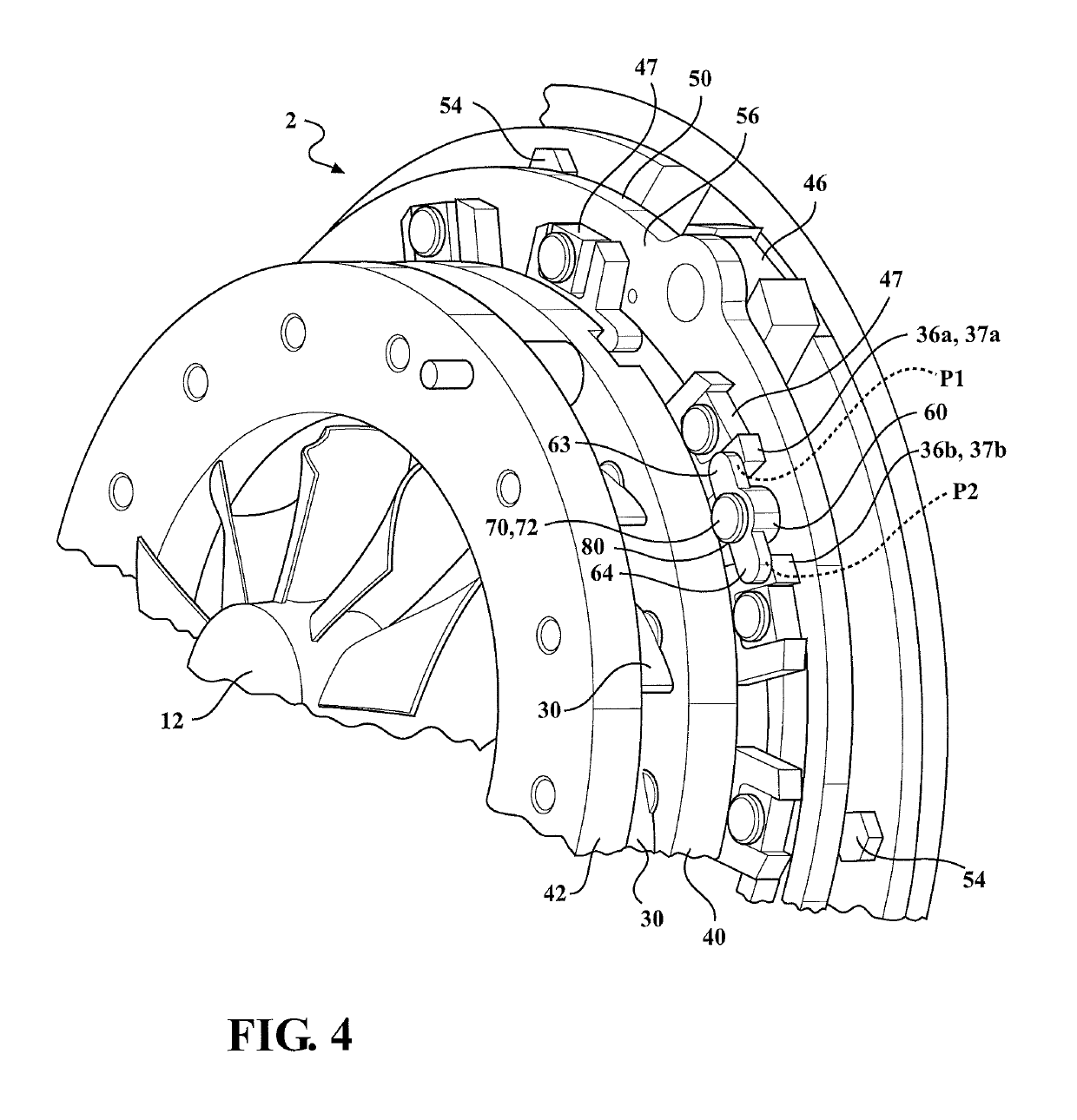
The result is a small amount of rotational and translational movement between the retention clips and the vane levers.

Method used


Image

  • Adjustment ring damper
  • Adjustment ring damper
  • Adjustment ring damper

Examples


Embodiment Construction

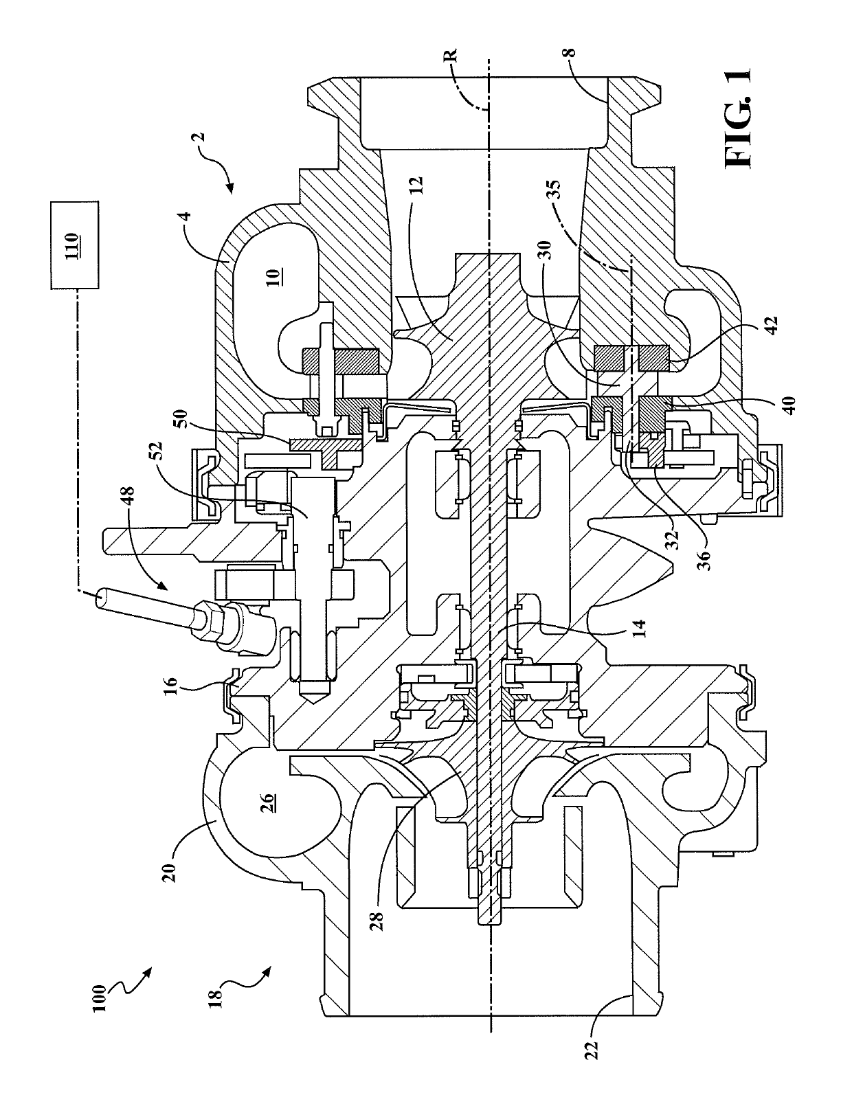
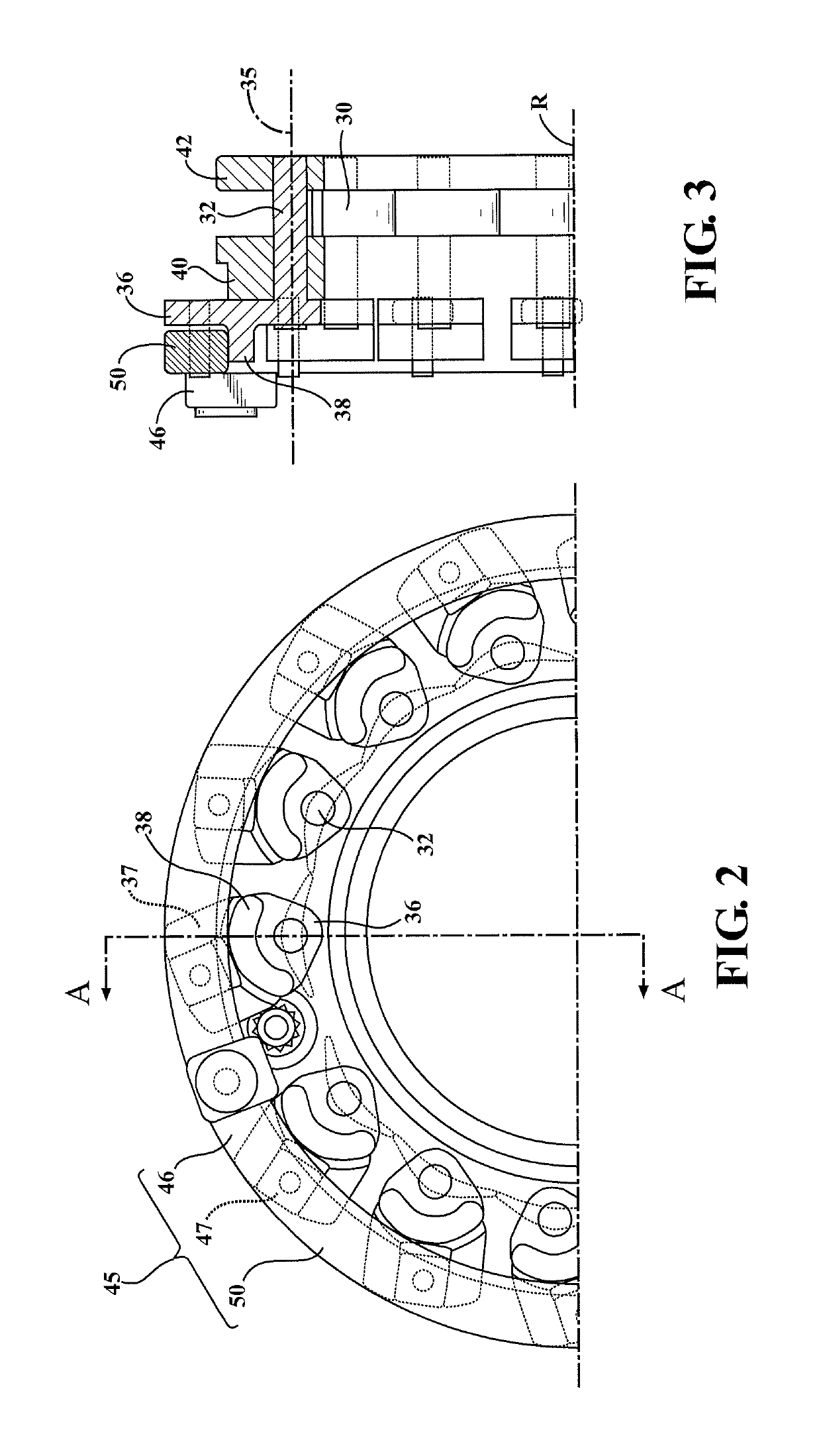
[0027]Referring to FIG. 1, an exhaust gas turbocharger 100 includes a turbine section 2, the compressor section 18, and a center bearing housing 16 disposed between and connecting the compressor section 18 to the turbine section 2. The turbine section 2 includes a turbine housing 4 that defines an exhaust gas inlet (not shown), an exhaust gas outlet 8, and a turbine volute 10 disposed in the fluid path between the exhaust gas inlet and the exhaust gas outlet 8. A turbine wheel 12 is disposed in the turbine housing 4 between the turbine volute 10 and the exhaust gas outlet 8. A shaft 14 is connected to the turbine wheel 12, is supported for rotation about a rotational axis R within in the bearing housing 16, and extends into the compressor section 18. The compressor section 18 includes a compressor housing 20 that defines an axially-extending air inlet 22, an air outlet (not shown), and a compressor volute 26. A compressor wheel 28 is disposed in the compressor housing 20 between the...


PUM


Abstract

A variable turbine geometry turbocharger (100) with an adjustment ring assembly (45) having an adjustment ring (50) and a series of pivotable guide vanes (30) that are operably connected to the adjustment ring (50). A spring-biased retention clip (60) is between adjacent vane levers (36) and is attached to the adjustment ring (50). The retention clip (60) applies a force against the adjacent vane levers (36) and dampens and reduces movement of corresponding components.

Description

CROSS-REFERENCE TO RELATED APPLICATION[0001]This application claims priority to and all the benefits of U.S. Provisional Application No. 61 / 915,850, filed on Dec. 13, 2013, and entitled “Adjustment Ring Damper,” which is incorporated herein by reference.BACKGROUND[0002]Field of the Disclosure[0003]This disclosure relates to turbochargers with Variable Turbine Geometry (VTG) in combination with a wastegate assembly. More particularly, this disclosure relates to actuating VTG guide vanes as well as a wastegate valve for controlling exhaust gas flow to a turbine wheel, such as with a common actuator.[0004]Description of Related Art[0005]Advantages of turbocharging include increased power output, lower fuel consumption, reduced pollutant emissions, and improved transient response. The turbocharging of engines is no longer primarily seen from a high-power performance perspective, but is rather viewed as a means of reducing fuel consumption and environmental pollution on account of lower ...

Claims


Application Information

Patent Timeline
Patent Type & Authority Patents(United States)
IPC IPC(8): F01D17/16F02B37/24F01D9/04
CPCF01D17/165F01D9/041F02B37/24Y02T10/144F05D2240/24F05D2260/30F05D2260/52F05D2220/40Y02T10/12
Inventor KENNEDY, DONALD MICHAEL
Owner BORGWARNER INC
Learn More