Supercharge Your Innovation With Domain-Expert AI Agents!

Object production

a technology of objects and production methods, applied in the direction of computer control, program control, instruments, etc., can solve the problems of long and expensive shimming process, difficult to produce separate airframe sections with sufficient precision,

Active Publication Date: 2018-07-17
BAE SYSTEMS PLC
View PDF38 Cites 2 Cited by
  • Summary
  • Abstract
  • Description
  • Claims
  • Application Information

AI Technical Summary

Benefits of technology

The present invention provides a method for producing an object by attaching a workpiece to a machining fixture, measuring the surface of the workpiece, and using the measurements to control the machining apparatus to produce the object. The method allows for accurate and efficient production of objects, particularly when attaching them to a system. The invention also provides apparatus for carrying out the method and an object produced using the method. The technical effects of the invention include improved accuracy and efficiency in producing objects and improved attachment of objects to a system.

Problems solved by technology

It tends to be very difficult to produce separate airframe sections with a sufficient level of precision to allow for easy assembly of the airframe.
Lengthy and expensive shimming processes may be required to fill gaps between the airframe sections when those sections are attached together.

Method used


Image

  • Object production
  • Object production
  • Object production

Examples


Embodiment Construction

[0037]It will be appreciated that relative terms such as horizontal and vertical, top and bottom, above and below, front and back, upper and lower, and so on, are used herein merely for ease of reference to the Figures, and these terms are not limiting as such, and any two differing directions or positions and so on may be implemented rather than truly horizontal and vertical, top and bottom, and so on.

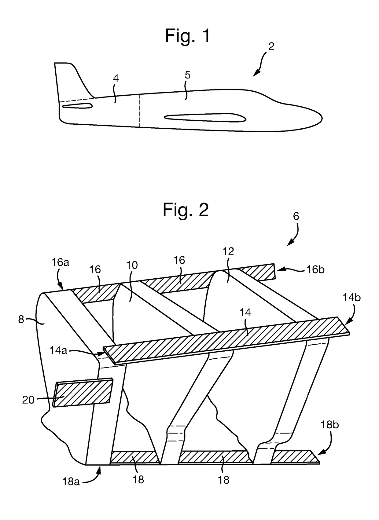
[0038]FIG. 1 is a schematic illustration (not to scale) of an example aircraft 2 comprising an aft fuselage 4, and an aircraft fore section 5. The aircraft fore section 5 includes a central fuselage to which the aft fuselage 4 is attached.

[0039]The aft fuselage 4 comprises an airframe and an aircraft skin fastened to the airframe. In this embodiment, the aft fuselage 4 comprises a port boom and a starboard boom that are mechanically attached together along a centreline. Each boom of the aft fuselage 4 comprises a plurality of structural components (for example, frames, keels, longeron...


PUM


Abstract

Disclosed is a method of producing an object, the method comprising: providing a workpiece comprising a plurality of attachment features for attaching the workpiece to a machining fixture; determining a datum, the datum being dependent upon the relative positions of the attachment features; measuring the surface of the workpiece with respect to the datum; providing the machining fixture; attaching, using the attachment features, the workpiece to the machining fixture; providing a digital model specifying the object including the attachment features; and, thereafter, using the measurements of the workpiece surface and the digital model, controlling machining apparatus with respect to the datum to machine the workpiece so as to produce the object as specified by the digital model.

Description

RELATED APPLICATIONS[0001]This application is a national phase application filed under 35 USC § 371 of PCT Application No. PCT / GB2015 / 051090 with an International filing date of Apr. 10, 2015 which claims priority of GB Patent Application 1407184.9 filed Apr. 24, 2014 and EP Patent Application 14275090.0 filed Apr. 24, 2014. Each of these applications is herein incorporated by reference in its entirety for all purposes.FIELD OF THE INVENTION[0002]The present invention relates to methods of producing objects.BACKGROUND[0003]Aircraft airframes typically comprise a plurality of frames (or formers) and longerons (or stringers / stiffeners). The frames are typically laterally spaced from one another and arranged perpendicular to the longitudinal axis of the aircraft. The primary purpose of formers is to establish the shape of the fuselage and reduce the column length of the longerons. The longerons are typically elongate members which are attached to the frames and are arranged parallel to...

Claims


Application Information

Patent Timeline
Patent Type & Authority Patents(United States)
IPC IPC(8): B64F5/00G05B19/4099B64F5/10G05B19/4097
CPCG05B19/4097G05B19/4099B64F5/10G05B2219/35134B64C1/06B64F5/00G05B19/402
Inventor BICKERSTAFF, JOHNWILSON, DAVID MARK
Owner BAE SYSTEMS PLC
Features
  • R&D
  • Intellectual Property
  • Life Sciences
  • Materials
  • Tech Scout
  • Unparalleled Data Quality
  • Higher Quality Content
  • 60% Fewer Hallucinations
Learn More