
Image processing apparatus and control method for applying spatial filters to images

a spatial filter and image processing technology, applied in image enhancement, image analysis, instruments, etc., can solve the problems of increasing the total number of transfer pixels, and unable to obtain sufficient recovery performance, so as to achieve efficient local image processing

Active Publication Date: 2018-07-17
CANON KK
View PDF6 Cites 18 Cited by
  • Summary
  • Abstract
  • Description
  • Claims
  • Application Information

AI Technical Summary

Benefits of technology

The present invention provides an image processing apparatus that can efficiently execute local image processing by dividing an image into multiple band area images and then applying a spatial filter to each band area image. The filter coefficients are set so as to refer to pixels for every K pixels in a direction, and the spatial filter is applied to each band area image K times to create different sampling phases. This results in better image quality and more efficient image processing.

Problems solved by technology

However, in the band processing or the block processing described in patent literature 1, since there are overlapping areas at the boundaries of the respective areas, if a reference area in the local image processing is widened, the total number of transfer pixels unwantedly increases.
For example, if an image in which a blur in an optical system occurs is recovered by spatial filter processing, it is impossible to obtain sufficient recovery performance unless the reference area of the spatial filter is set to have the spread as large as a blur width, as shown in FIG. 19.
If, therefore, the blur in the optical system is large, it is necessary to widen the reference area, resulting in an increase in the total number of transfer pixels.
Therefore, if the noise in the imaging system is large, it is necessary to widen the reference area, resulting in an increase in the total number of transfer pixels.

Method used


Image

  • Image processing apparatus and control method for applying spatial filters to images
  • Image processing apparatus and control method for applying spatial filters to images
  • Image processing apparatus and control method for applying spatial filters to images

Examples


first embodiment

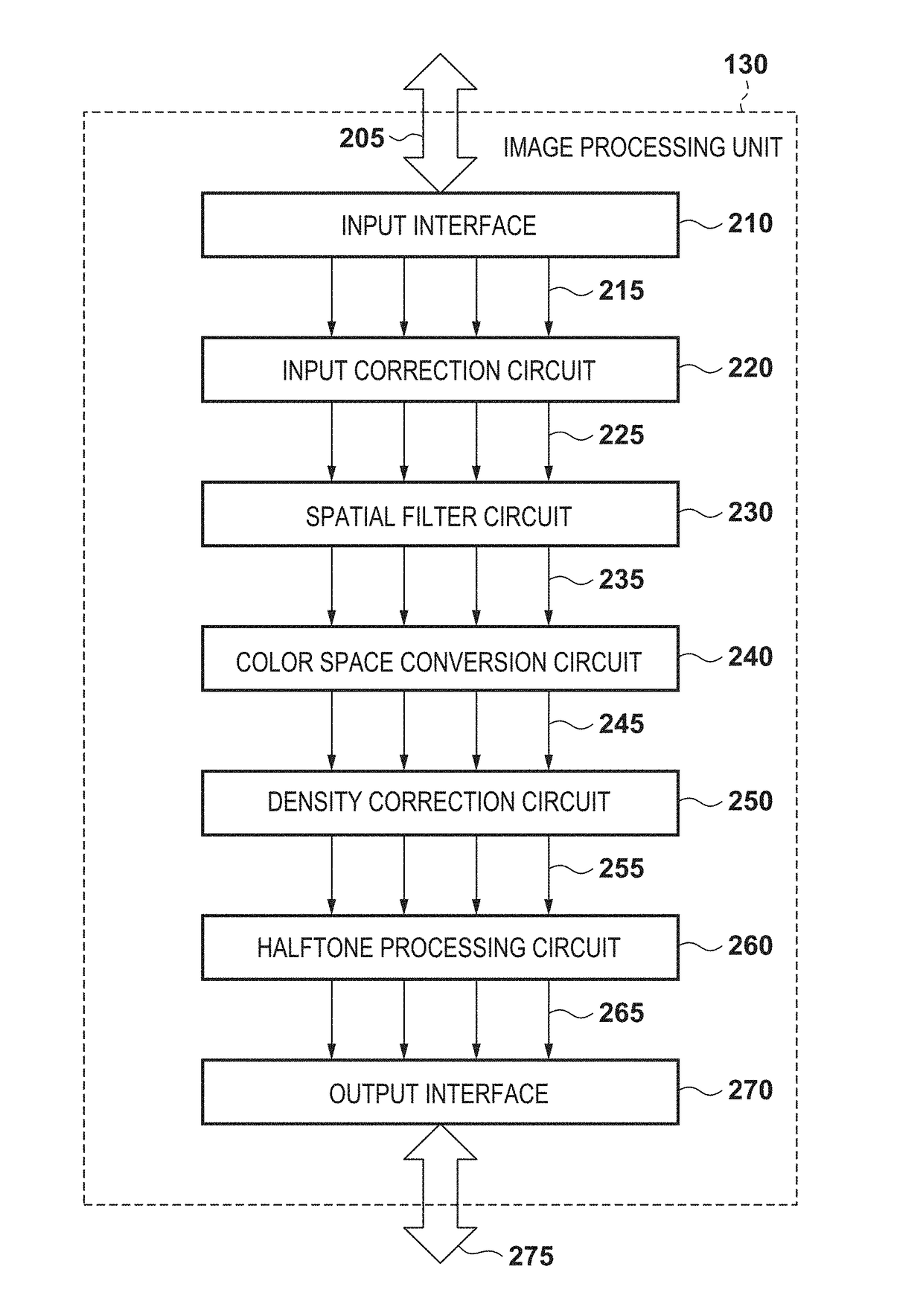
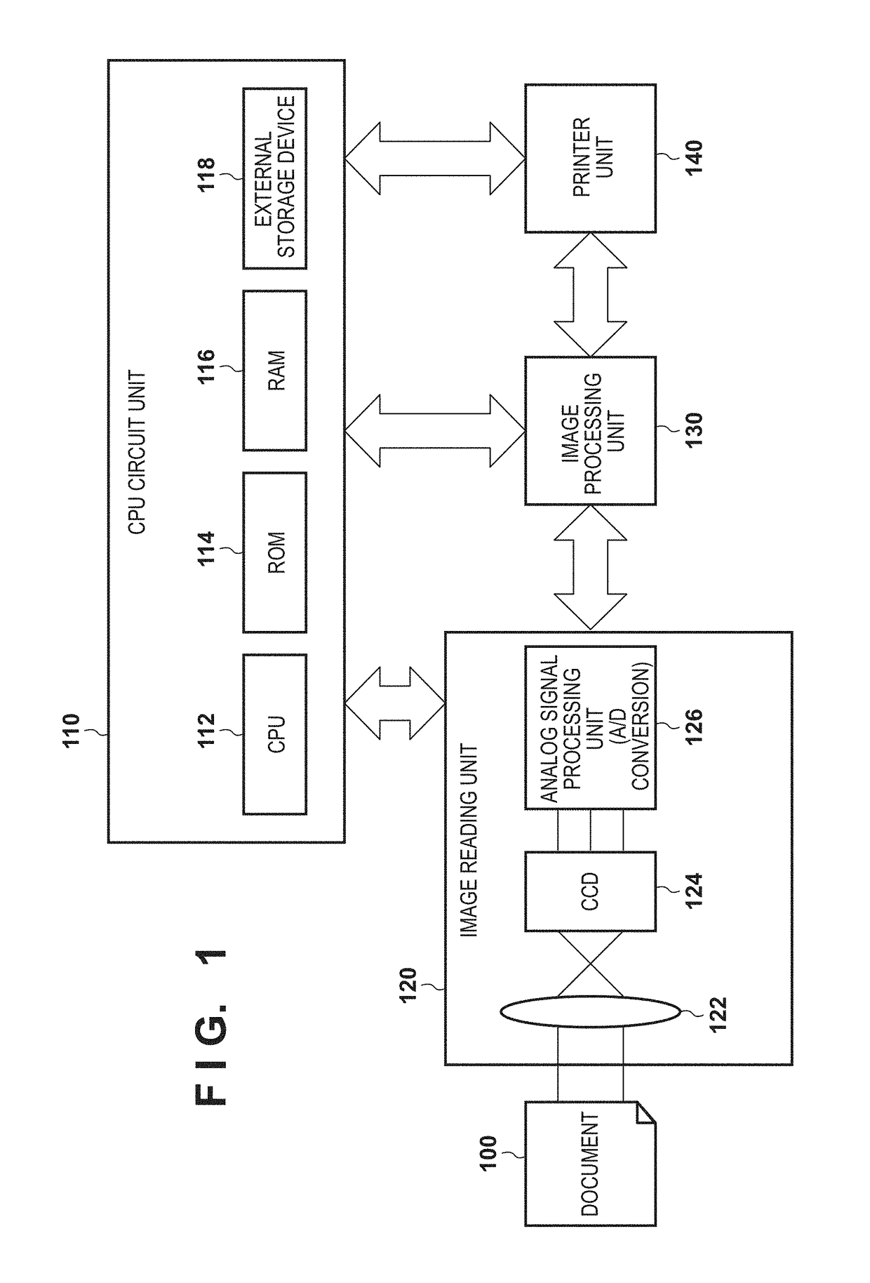
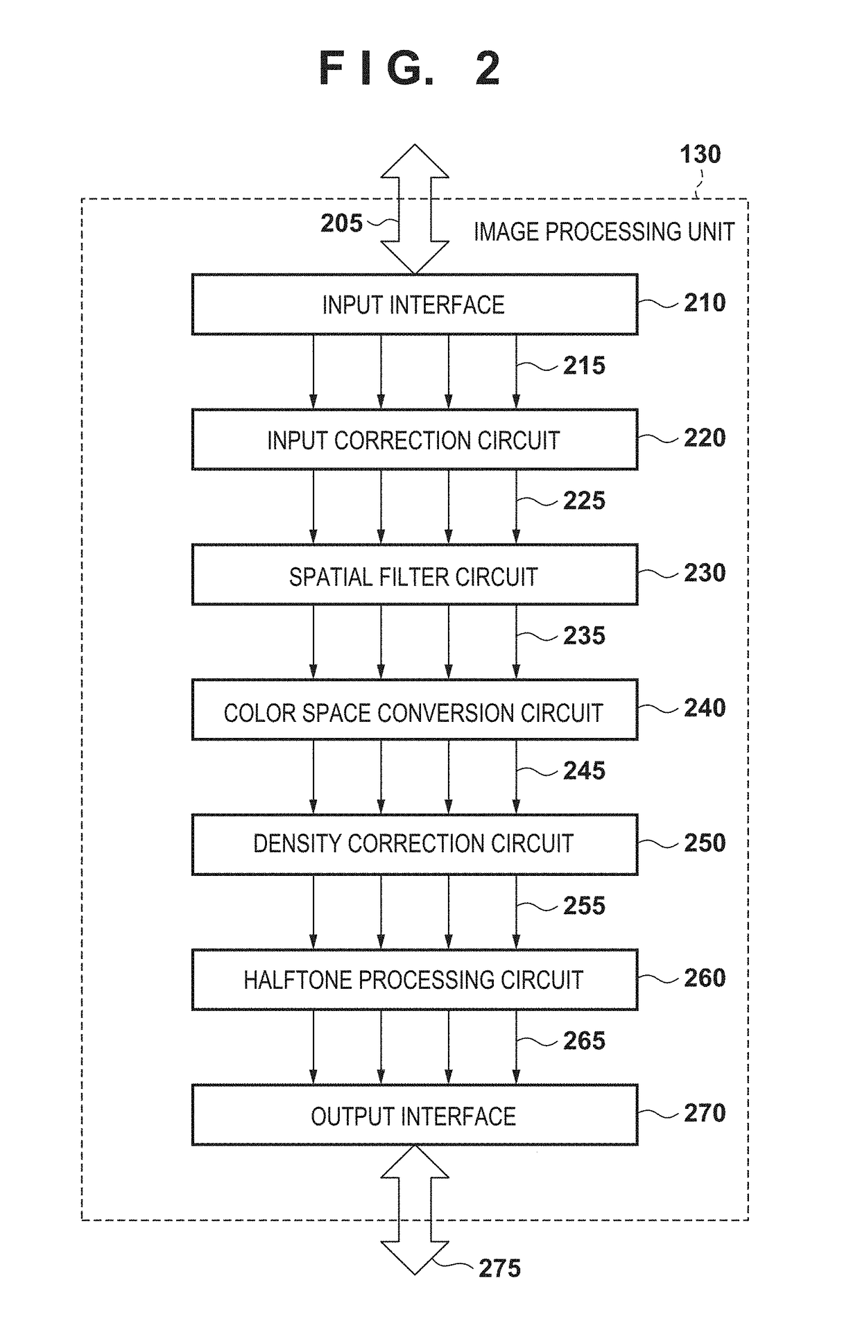
[0033]As the first embodiment of an image processing apparatus according to the present invention, a multi-function peripheral (MFP) for reading a document, correcting (compensating for) an image blur caused by a reading optical system, and performing image forming will be exemplified below.

[0034]

[0035]The image processing method described in “BACKGROUND OF THE INVENTION” as the technical premise of the present invention will be explained first.

[0036]Block Processing

[0037]In this method, digital image data is divided into a plurality of block (tile) areas, and local (vicinity) image processing is separately performed. In this technique, to perform local (vicinity) image processing without any gap between the block areas, each block area is made to partially overlap an adjacent block area at the boundary. This can define a memory capacity by the size of each block (tile) area, thereby saving the memory capacity. Assume, for example, that A4-size digital image data (5,000 pixels in th...

second embodiment

[0093]The second embodiment will describe another method of thinning out the reference pixels of a spatial filter. That is, although the reference pixels are thinned out for every other row in the first embodiment, the thinning out method is not limited to this.

[0094]Note that in Examples 1 to 4 to be described below, the size of a reference area is set to a 5-by-5 pixel square (a width fw=5 and a height fh=5), similarly to the conventional band processing (FIG. 3). An equal delay memory capacity is set.

example 1 (

Column Thinning Out)

[0095]FIG. 8 is a view for explaining spatial filter processing according to the second embodiment. In this example, as shown in 800a, a reference area of a 5-by-5 pixel square is thinned out for every other column. In this case, processing for one band area is divided into two processes, that is, processing for pixels of even-numbered columns and processing for pixels of odd-numbered columns, as shown in 800b and 800c. Note that 800b and 800c each show processing for a band area 301 as an example. However, the same processing method is used for the remaining band areas.

[0096]In the example of FIG. 8, as a result of dividing the processing into the two processes, the band area has a height Bdh of 16 pixels, which is twice that in the conventional processing. Therefore, as shown in 800d, an increasing rate r of the total number of transfer pixels is about 1.33. As compared with the conventional band processing shown in 300d, the increasing rate r of the total numb...


PUM


Abstract

An image processing apparatus divides an input image into a plurality of band area images, stores the respective band area images in a band memory, and performs image processing. The apparatus comprises: a storage unit configured to store filter coefficients having a two-dimensional reference area of M pixels in a first direction and N pixels in a second direction orthogonal to the first direction; and a spatial filter unit configured to apply, to the band area image stored in the band memory, a spatial filter using the filter coefficients. The filter coefficients are set as the filter coefficients so as to refer to pixels for every K pixels in the second direction, and the spatial filter unit sequentially applies the spatial filter to the band area image K times in the second direction.

Description

BACKGROUND OF THE INVENTION[0001]Field of the Invention[0002]The present invention relates to an image processing technique using a spatial filter.[0003]Description of the Related Art[0004]When performing image forming and outputting an image, local image processing such as spatial filter processing is conventionally performed. This local image processing indicates image processing of performing some calculation using all pixels included in a reference area including a pixel (to be referred to as a processing pixel hereinafter) to be processed. For example, spatial filter processing such as edge emphasis processing or blur processing is performed for digital image data.[0005]Such local image processing may use a method of processing a pixel array at the upper end of digital image data from the left end to the right end, processing the second pixel array from the upper end, and repeatedly executing the same processing up to a pixel array at the lower end. In this method, as the width...

Claims


Application Information

Patent Timeline
Patent Type & Authority Patents(United States)
IPC IPC(8): H04N1/409G06T5/20H04N1/407H04N1/405H04N1/60H04N1/58
CPCH04N1/409G06T5/20H04N1/405H04N1/4072H04N1/58H04N1/6027H04N1/6008H04N2201/0094G06T2207/10024G06T2207/20024G06T2207/30176G06T1/60
Inventor FUSE, KOJIYANAI, TOMOKAZUISHIKAWA, HISASHIYAMADA, AKITOSHIKATO, MINAKO
Owner CANON KK
Learn More