This helps you quickly interpret patents by identifying the three key elements:
Problems solved by technology
Method used
Benefits of technology
Benefits of technology
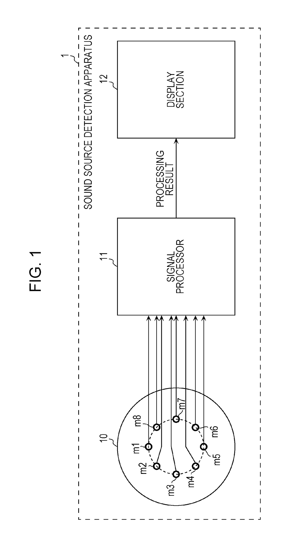
The present invention is about a device that can better locate the position of a sound source. It includes multiple microphones that are placed on a surface of a buffle, which prevents direct sound from being picked up from certain directions. This allows the device to accurately detect the location of a sound source in a target area.
Problems solved by technology
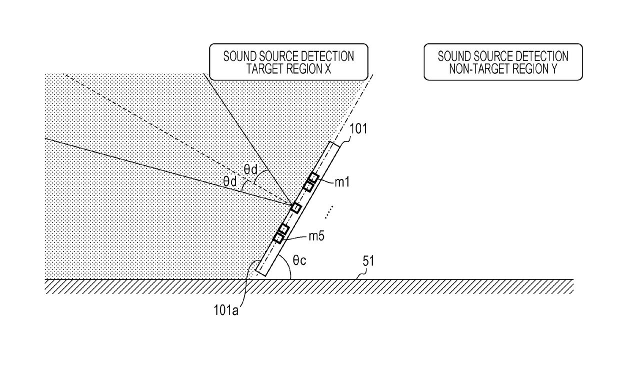
However, such a conventional sound source localization apparatus as that disclosed in Japanese Unexamined Patent Application Publication No. 2011-124749 is undesirably unable to distinguish between sound sources (a sound source at the front surface side and a sound source at the back surface side) that have symmetry with respect to the array plane of the microphone array, as the phase difference between sound waves from one of the sound sources is equal to the phase difference between sound waves from the other sound source.
That is, under the influence of the sound source at the back surface side, which is not a detection target region, of the sound source localization apparatus, the conventional sound source localization apparatus may be unable to detect the sound source located in a space at the front surface side, which is a detection target region, of the sound source localization apparatus.
Method used
Image
Click on the blue label to locate the original text in one second.
Reading with bidirectional positioning of images and text.
Examples
modification 1
[0090]FIG. 12 is a diagram showing an example of arrangement of a microphone array 102A of a sound pickup device 10A according to Modification 1. Constituent elements that are identical to those shown in FIG. 2 are given the same reference numerals, and as such, they are not described in detail.
[0091]In the embodiment described above, the plurality of microphone elements constituting the microphone array 102 have been described as being arrayed in an annular shape. However, this does not imply any limitation. For example, the plurality of microphone elements may be arrayed in a pentagonal shape or an octagonal shape. This is because the interval between two microphone elements determines a measurable frequency (upper-limit frequency). Further, for example, the plurality of microphone elements constituting the microphone array 102A may be arrayed as shown in FIG. 12.
[0092]In the example shown in FIG. 12, the plurality of microphone elements constituting the microphone array 102A cons...
modification 2
[0093]FIG. 13 is a diagram showing an example of a buffle section 101B of a sound pickup device 10B according to Modification 2.
[0094]In the embodiment describes above, the buffle section 101 has been described as a circular plate member. However, the buffle section 101 does not necessarily need to be circular. For example, as shown in FIG. 13, the buffle section 101 may alternatively be a rectangular plate member.
[0095]In this case, the length of a side of the buffle section 101B can be calculated on the basis of the maximum length of intervals between the plurality of microphone elements and a predetermined angle.
[0096]More specifically, the diameter d1 of the buffle section 101 needs only be taken as the length d1 of a side of the buffle section 101B, and the length d1 of a side of the buffle section 101B needs only be calculated to satisfy the relationship of (Eq. 4). That is, the length d1 of a side of the buffle section 101B needs only be calculated to satisfy the relationship...
modification 3
[0097]FIG. 14 is a diagram showing an example of arrangement of a microphone array 102 of a sound pickup device 100 according to Modification 3.
[0098]In the embodiment described above (e.g., FIG. 2, etc.) and Modification 2 (e.g., FIG. 13, etc.), the descriptions are based on the premise that the center position of the buffle section coincides with the center position of the microphone array (microphone elements m1 to m8). However, this does not imply any limitation. As shown in FIG. 14, the center position of the buffle section 101B does not need to coincide with the center position of the microphone array 102 (microphone elements m1 to m8).
PUM
Abstract
A sound source localization apparatus is provided which can more surely detect a sound source located in a detection target region. The sound source localization apparatus includes a plurality of microphones and a baffle. The baffle has a first surface and a second surface. The second surface is a surface opposite to the first surface. The plurality of microphones are two-dimensionally arrayed and fixed in the first surface. The baffle allows the plurality of microphones to pick up direct sound arriving at the first surface and prevents the plurality of microphones from picking up direct sound arriving at the second surface.
Description
BACKGROUND[0001]1. Technical Field[0002]The present disclosure relates to a sound source localization apparatus.[0003]2. Description of the Related Art[0004]There has been proposed a sound source localization apparatus that performs sound source localization on the basis of the phase differences between sounds (sound waves) that are generated when the sounds arrive at a microphone array of microphones arrayed in the same plane (for example, see Japanese Unexamined Patent Application Publication No. 2011-124749).[0005]Such a sound source localization apparatus as that disclosed in Japanese Unexamined Patent Application Publication No. 2011-124749 has the advantages of being simple in structure and high in installability.[0006]However, such a conventional sound source localization apparatus as that disclosed in Japanese Unexamined Patent Application Publication No. 2011-124749 is undesirably unable to distinguish between sound sources (a sound source at the front surface side and a so...
Claims
Application Information
Patent Timeline
Application Date:The date an application was filed.
Publication Date:The date a patent or application was officially published.
First Publication Date:The earliest publication date of a patent with the same application number.
Issue Date:Publication date of the patent grant document.
PCT Entry Date:The Entry date of PCT National Phase.
Estimated Expiry Date:The statutory expiry date of a patent right according to the Patent Law, and it is the longest term of protection that the patent right can achieve without the termination of the patent right due to other reasons(Term extension factor has been taken into account ).
Invalid Date:Actual expiry date is based on effective date or publication date of legal transaction data of invalid patent.

