Recording apparatus with an enhanced medium support structure

a technology of supporting structure and recording apparatus, which is applied in the direction of printing, other printing apparatus, etc., can solve the problems of affecting recording quality, deviation of landing position on the sheet, and inability to stably maintain the position of the sheet, so as to reduce the likelihood of the front end and achieve stably the flatness of the medium

Active Publication Date: 2018-07-24
SEIKO EPSON CORP
View PDF9 Cites 0 Cited by
  • Summary
  • Abstract
  • Description
  • Claims
  • Application Information

AI Technical Summary

Benefits of technology

[0008]Advantageous effects will be described. According to an aspect of the invention, a recording apparatus includes a supporting portion that supports a medium transported and includes a recording head that is fixedly disposed at a position opposing the supporting portion and records by using liquid on the medium supported by the supporting portion. The recording head has a plurality of nozzle rows each including a plurality of nozzles that eject the liquid, and the plurality of nozzle rows are arranged side by side in the recording head along a width direction of the medium that intersects a transport direction of the medium. The supporting portion has a dumping portion including a position opposite the nozzle rows of the recording head, and the dumping portion is capable of receiving the liquid ejected from the nozzle rows when the recording head performs flushing. The supporting portion also has a supporting surface capable of supporting the medium at a position not opposite the nozzle rows of the recording head. The dumping portion has a slope disposed in at least part of a region adjoining the supporting surface, and the slope is disposed in continuity with the supporting surface and inclined upward toward the supporting surface.
[0009]With this configuration, even when part of the medium transported over the supporting surface of the supporting portion falls into the dumping portion, the medium can be supported by the slope provided in the dumping portion. In other words, even the positions in the supporting portion that are opposite the nozzle rows of the recording head can contribute to supporting of the medium. Thus, this configuration may stably obtain the flatness of the medium supported by the supporting portion that allows the recording head for ejecting liquid to perform flushing.
[0010]In the recording apparatus, it is preferable that the supporting surface be configured to include an upper surface of a protrusion protruding upward from the dumping portion and that the slope is provided at a position on the upstream side of the protrusion in the transport direction.
[0011]This configuration can reduce the likelihood of the front end of the transported medium being caught by the protrusion.
[0012]In the recording apparatus, it is preferable that the slope be also provided at a position on the downstream side of the protrusion in the transport direction.
[0013]With this configuration, even when the rear end of the medium transported falls into the dumping portion, the medium can be supported by the slope provided on the downstream side of the protrusion.

Problems solved by technology

However, the printer described in JP-A-2004-9667 may not stably maintain the position of the sheet transported over the supporting portion because the sheet is supported by the supporting portion only with the portions (the protrusions) opposite the spacings between the nozzle groups provided in the head.
A tilted or warped sheet on the supporting portion results in the deviation of landing positions on the sheet by the ink ejected from the nozzles of the head.
This may affect recording quality.

Method used


Image

  • Recording apparatus with an enhanced medium support structure
  • Recording apparatus with an enhanced medium support structure
  • Recording apparatus with an enhanced medium support structure

Examples


first embodiment

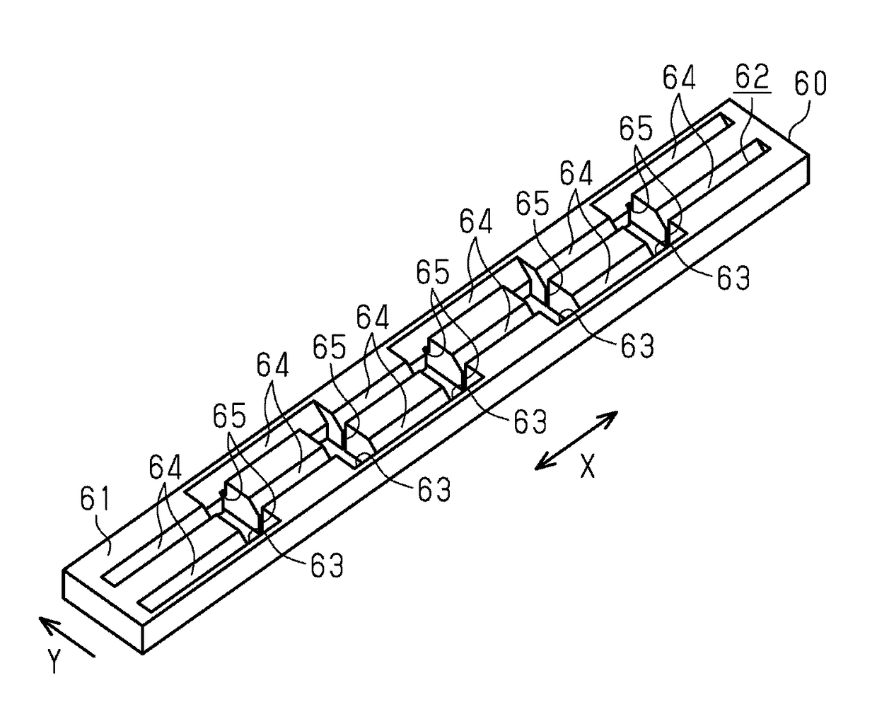
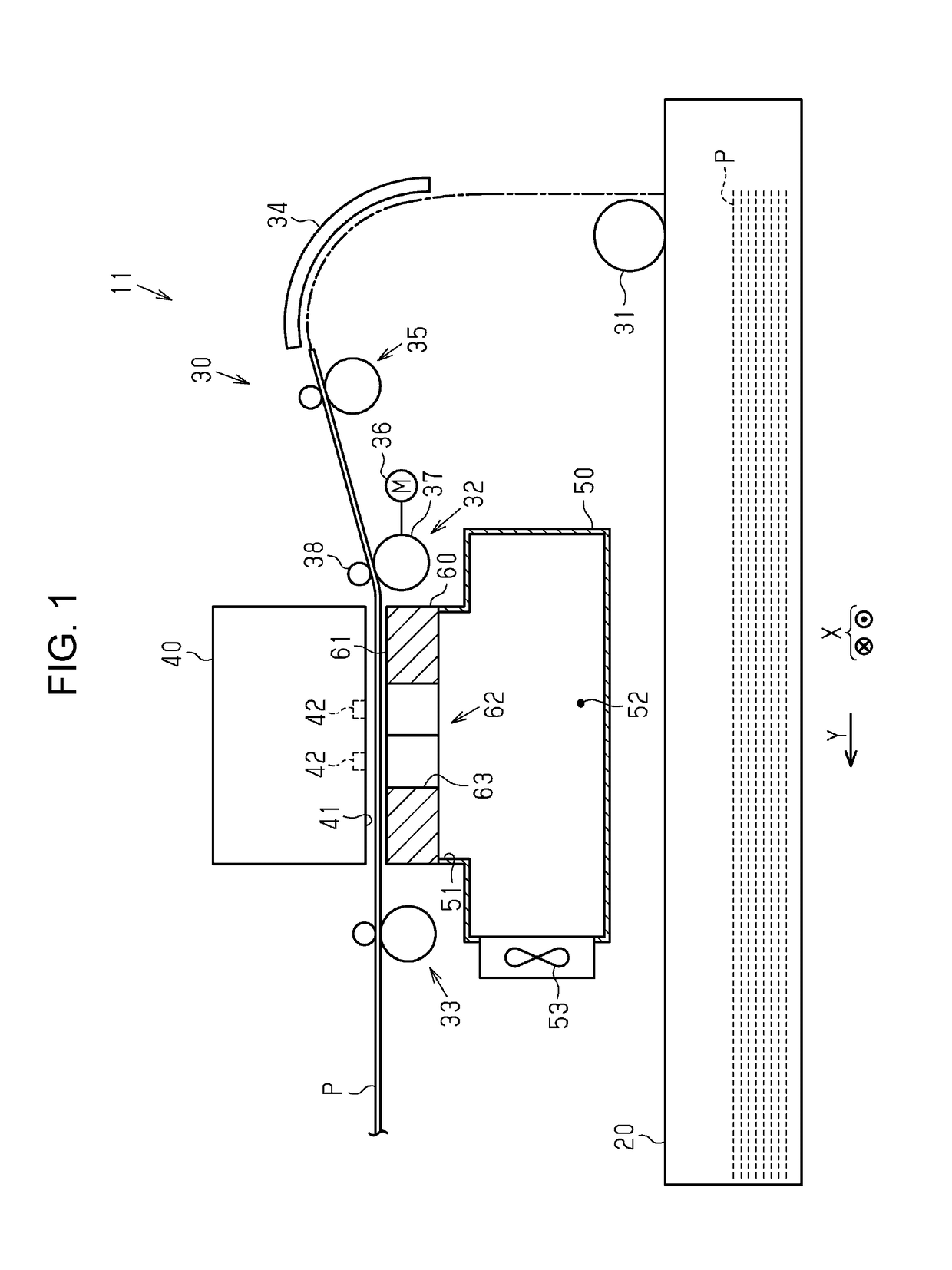
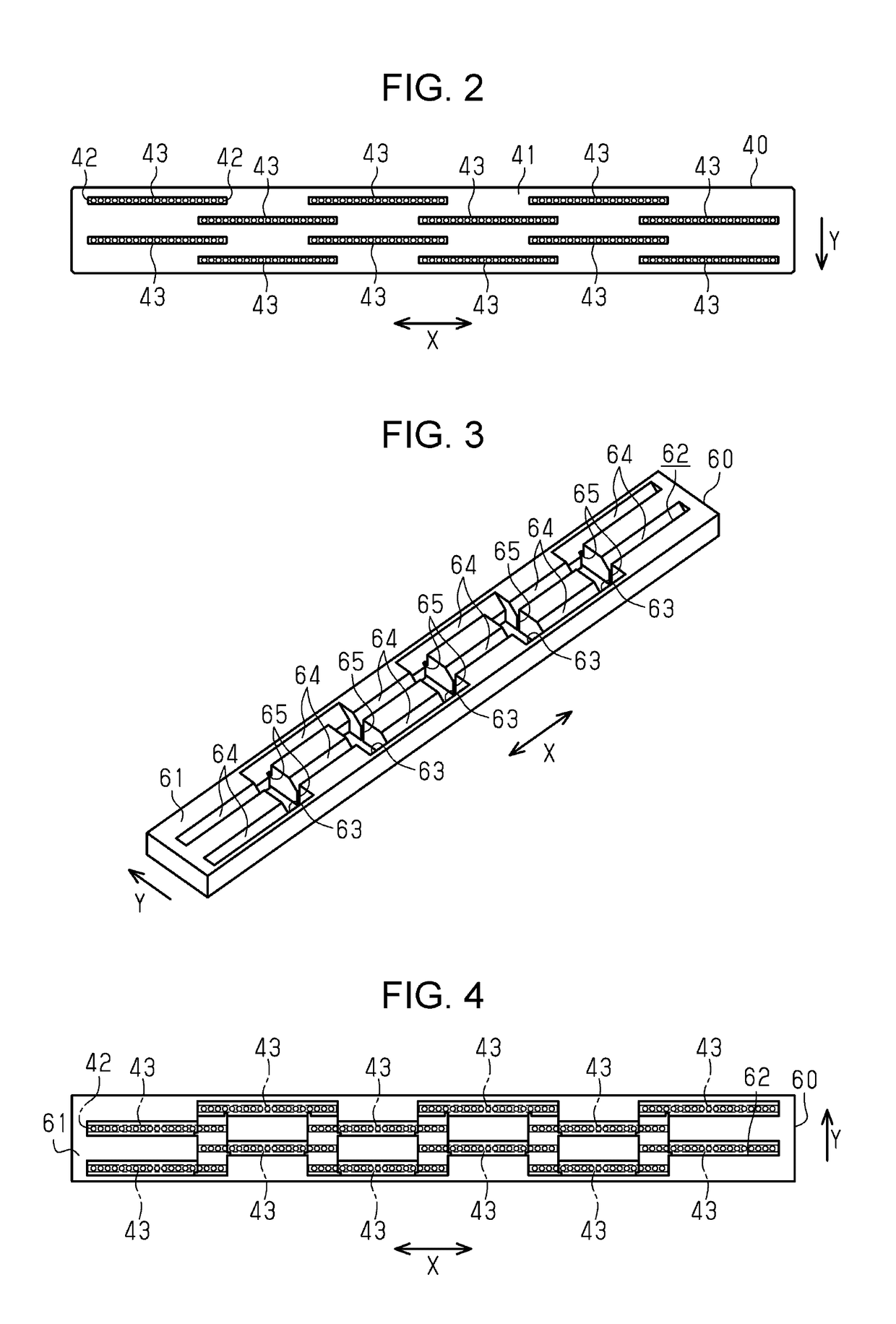
[0068]As illustrated in FIG. 1, a recording apparatus 11 according to a first embodiment of the invention includes a paper cassette 20 capable of storing stacked sheets of paper P (otherwise referred to as “sheets P”), which is an example of a medium, a transport section 30 for transporting each sheet P contained in the paper cassette 20, a supporting portion 60 for supporting the sheet P transported by the transport section 30 from underneath the sheet P, and a recording head 40 for recording on the sheet P supported by the supporting portion 60. Note that a direction in which the sheet P is transported over the supporting portion 60 (i.e., a direction from the right side toward the left side of FIG. 1) is hereinafter referred to as the transport direction Y of the sheet P, and a direction intersecting the transport direction Y is referred to as the width direction X of the sheet P.

[0069]The transport section 30 includes a pickup roller 31 for sending out each sheet P that is locat...

second embodiment

[0080]Next, a recording apparatus 11 according to a second embodiment will be described. In the recording apparatus 11 according to the second embodiment, the configuration of the supporting portion 60 for supporting the sheet P is different from that of the first embodiment while other configurations are similar to those of the first embodiment. Thus, no further description is provided for the portion having the similar configuration.

[0081]As illustrated in FIGS. 7, 8, and 9, the supporting portion 60 of the second embodiment has slits 66 as part of the dumping portion 62. Each slit 66 has an opening of which the width in the transport direction Y is smaller than that of the through-hole 63. In FIG. 8, through-holes 63 are formed at the lowest end of each slope 64 at two positions along the width direction X. This slit 66 is provided at a position next to a through-hole 63 and on the upstream side of a slope 64 in the transport direction Y. The slit 66 passes through the supporting...

third embodiment

[0083]Next, a recording apparatus 11 according to a third embodiment will be described. In the recording apparatus 11 according to the third embodiment, the configuration of the supporting portion 60 for supporting the sheet P is different from that of the first embodiment while other configurations are similar to those of the first embodiment. Thus, no further description is provided for the portion having the similar configuration.

[0084]As illustrated in FIGS. 10, 11, and 12, the supporting portion 60 according to the third embodiment has separate dumping portions 62 at positions opposite respective nozzle rows 43 of the recording head 40. In other words, the supporting portion 60 has the same number of dumping portions 62 as that of the nozzle rows 43 included in the recording head 40. Each dumping portion 62 has a slope 64 inclined upward from the upstream side toward the downstream side in the transport direction Y. Each dumping portion 62 also has a through-hole 63 passing thr...


PUM


Abstract

A recording apparatus includes a supporting portion that supports a sheet of paper transported and a recording head fixedly disposed at a position opposing the supporting portion, for recording. The recording head has nozzle rows for ejecting ink, and the nozzle rows are arranged side by side in the recording head in a direction intersecting a transport direction of the sheet. The supporting portion has a dumping portion including a position opposite the nozzle rows of the recording head, and the dumping portion is capable of receiving the ink ejected from the nozzle rows when the recording head performs flushing. The supporting portion has a supporting surface capable of supporting the sheet at a position not opposite the nozzle rows of the recording head. A slope inclining relative to the supporting surface is disposed in at least part of the boundary region between the dumping portion and the supporting surface.

Description

CROSS REFERENCES TO RELATED APPLICATIONS[0001]The entire disclosure of Japanese Patent Application No. 2016-054961, filed Mar. 18, 2016 is expressly incorporated by reference herein.BACKGROUND[0002]1. Technical Field[0003]The present invention relates to recording apparatuses such as, for example, ink jet printers.[0004]2. Related Art[0005]There is known an ink jet printer, which is a type of recording apparatus, having a head fixedly disposed at a position opposite a supporting portion that supports a sheet of paper, which is an example of a medium. The head has a plurality of nozzles that eject ink, which is an example of liquid, to record on the sheet of paper transported over the supporting portion. This type of printer is desired to perform “flushing” to discharge the ink inside the nozzles as needed in order to maintain and recover ink ejecting properties of the nozzles in the head. JP-A-2004-9667 describes a printer that has a head including a plurality of nozzle groups, each...

Claims


Application Information

Patent Timeline
Patent Type & Authority Patents(United States)
IPC IPC(8): B41J2/165B41J11/06
CPCB41J2/16526B41J11/06B41J2/16585B41J2/01B41J2/14
Inventor MORI, KAZUNORI
Owner SEIKO EPSON CORP
Why Eureka
Try Eureka