Shielding cover

A technology of shielding cover and shielding frame is applied in the field of shielding cover, which can solve the problems of high mold development cost and mold repair cost, difficult disassembly, etc., so as to save mold development cost and mold repair cost, and reduce mold process, size and flatness. stable effect

Pending Publication Date: 2017-10-13
SHENZHEN SUNWAY COMM
View PDF12 Cites 0 Cited by
  • Summary
  • Abstract
  • Description
  • Claims
  • Application Information

AI Technical Summary

Problems solved by technology

[0004] The shielding cover disclosed in the above-mentioned patent adopts the fixing method in which the above-mentioned convex shell is hooked in the through hole, but this shielding cover still cannot solve the above-mentioned technical problems of difficulty in disassembly, high cost of mold development and mold repair

Method used


Image

  • Shielding cover
  • Shielding cover
  • Shielding cover

Examples


Embodiment 1

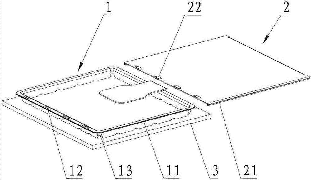
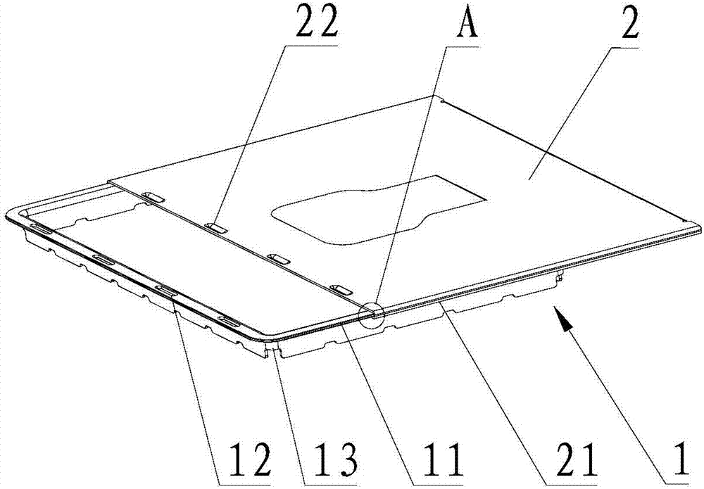
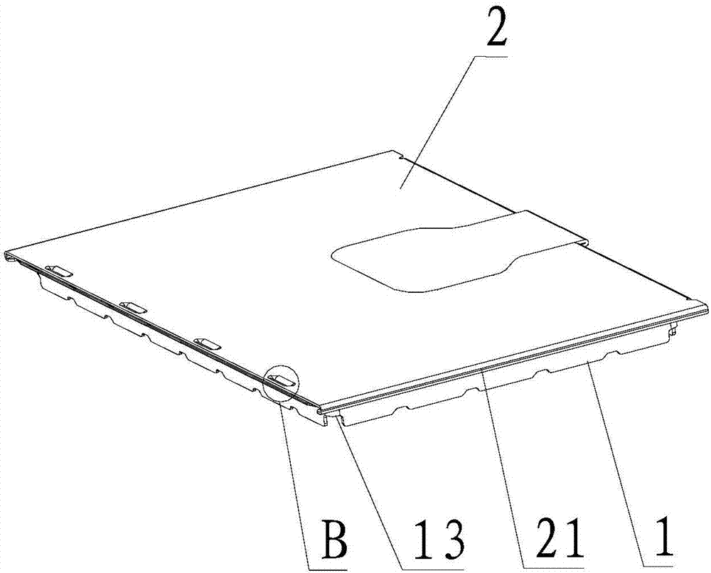
[0051] Please refer to Figure 1-5 , Embodiment 1 of the present invention is:

[0052] The shielding case of the present embodiment comprises a shielding frame 1, a shielding cover 2, a semi-stretched structure 13 and a plate-shaped PCB3, the shielding frame 1 is located on the PCB3, and the shielding frame 1 includes a first frame body, a second frame body, the third frame body and the fourth frame body, the first frame body, the second frame body, the third frame body and the fourth frame body respectively include a top surface and a side surface connected with the top surface, and the first frame body The top surfaces of the frame body, the second frame body, the third frame body and the fourth frame body are integrally formed, and the sides of the first frame body, the second frame body, the third frame body and the fourth frame body pass through The semi-tensile structures 13 are connected. The edge positions of the top surfaces of the first frame body and the third fr...


PUM


Abstract

The invention relates to a shielding cover. The shielding cover comprises a shielding rack and a shielding cover, wherein an edge part is arranged at an edge position of the shielding rack and outwards extends along a length direction, an edge position of the shielding cover is inwards bent along a length direction to form a bending groove, at least one concave structure is arranged on an upper surface of the shielding rack, at least one convex structure is arranged on a lower surface of the shielding cover and is adaptive to the concave structure, and the edge part is inserted into the bending groove from a groove opening of the bending groove until the convex structure is clamped into the concave structure. The shielding cover has the advantages that the die development cost and the die repair cost are reduced, the production efficiency is improved, and the production cost is reduced.

Description

technical field [0001] The invention relates to electronic shielding technology, in particular to a shielding cover. Background technique [0002] The shielding cover generally includes a shielding bracket and a cover. In the prior art, the assembly of the shielding bracket and the cover adopts a hole and a convex hull structure. Therefore, it is necessary to form multiple convex hulls or hole features on the mold, and the forming punch is easy to wear And breakage, resulting in the risk of fuzz or plugging holes in the product holes after molding, as well as the shortness of the convex hull and the risk of rupture. In addition, the frequency of mold punch damage is high, increasing mold repair and reducing production efficiency. In addition, when electronic components need to be replaced or repaired, it is difficult to disassemble the existing shielding cover structure, and the shielding cover and electronic components on the PCB are easily damaged during disassembly, and ...

Claims


Application Information

Patent Timeline
Patent Type & Authority Applications(China)
IPC IPC(8): H05K9/00
CPCH05K9/0007
Inventor 文盛杨
Owner SHENZHEN SUNWAY COMM
Why Eureka
Try Eureka