Supercharge Your Innovation With Domain-Expert AI Agents!

Optical nondestructive testing method and optical nondestructive testing apparatus

a testing method and optical technology, applied in the direction of optical radiation measurement, material flaw investigation, instruments, etc., can solve the problems of inability to use the thermal diffusivity measurement and the inability to sufficiently propagate heat from the surface of the sampl

Active Publication Date: 2018-07-24
JTEKT CORP
View PDF6 Cites 1 Cited by
  • Summary
  • Abstract
  • Description
  • Claims
  • Application Information

AI Technical Summary

Problems solved by technology

This conventional method unfortunately requires breaking a sample in order to check the state of connection.
This means that the thermal diffusivity measured is unusable for determining the state of connection between first and second members of a measurement object connected to each other directly or connected to each other with a connector interposed therebetween.
This means that heat has to be sufficiently propagated from the surface of the sample to the underside of the sample.

Method used


Image

  • Optical nondestructive testing method and optical nondestructive testing apparatus
  • Optical nondestructive testing method and optical nondestructive testing apparatus
  • Optical nondestructive testing method and optical nondestructive testing apparatus

Examples


Embodiment Construction

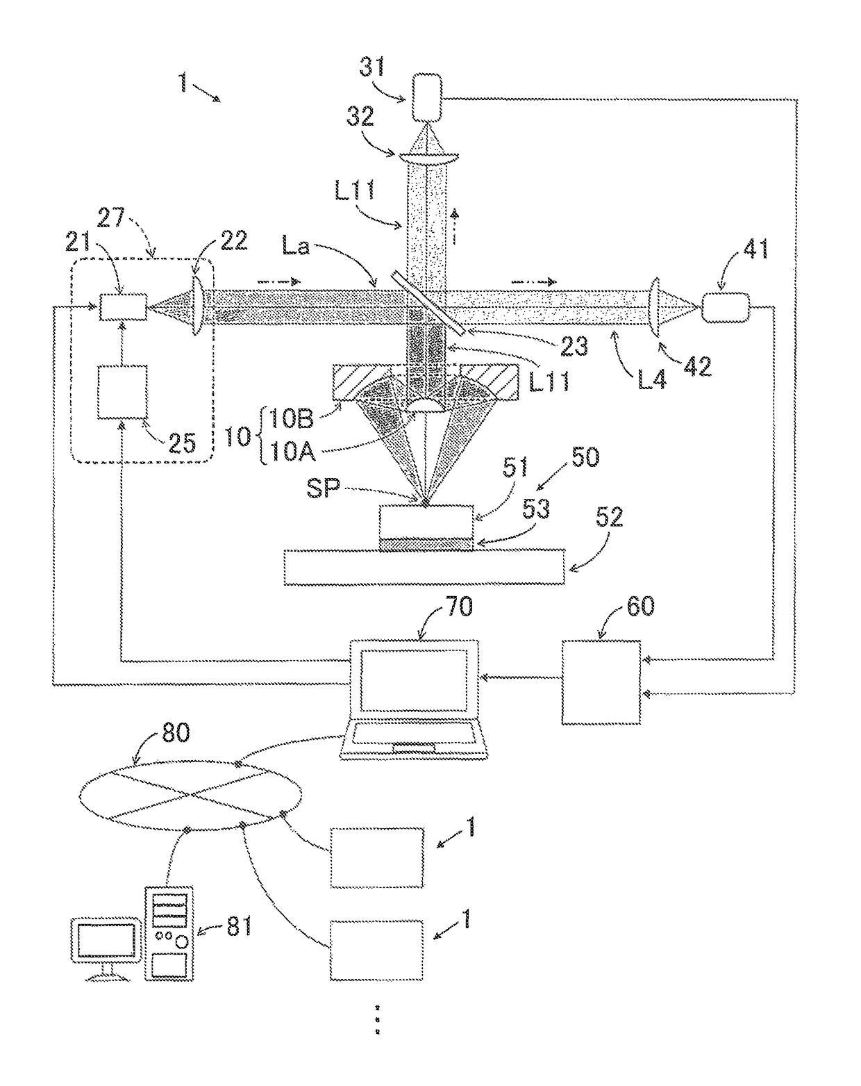
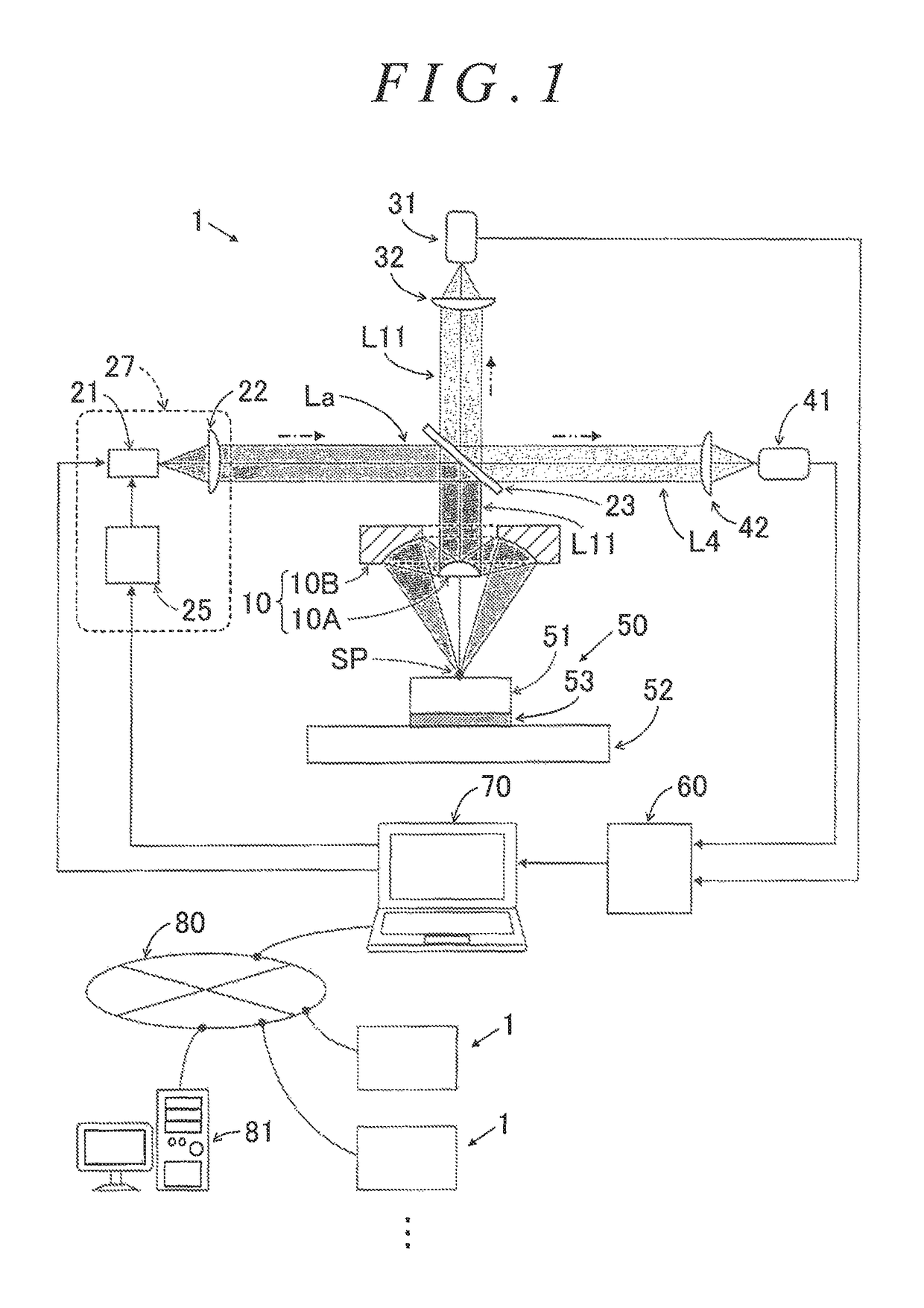
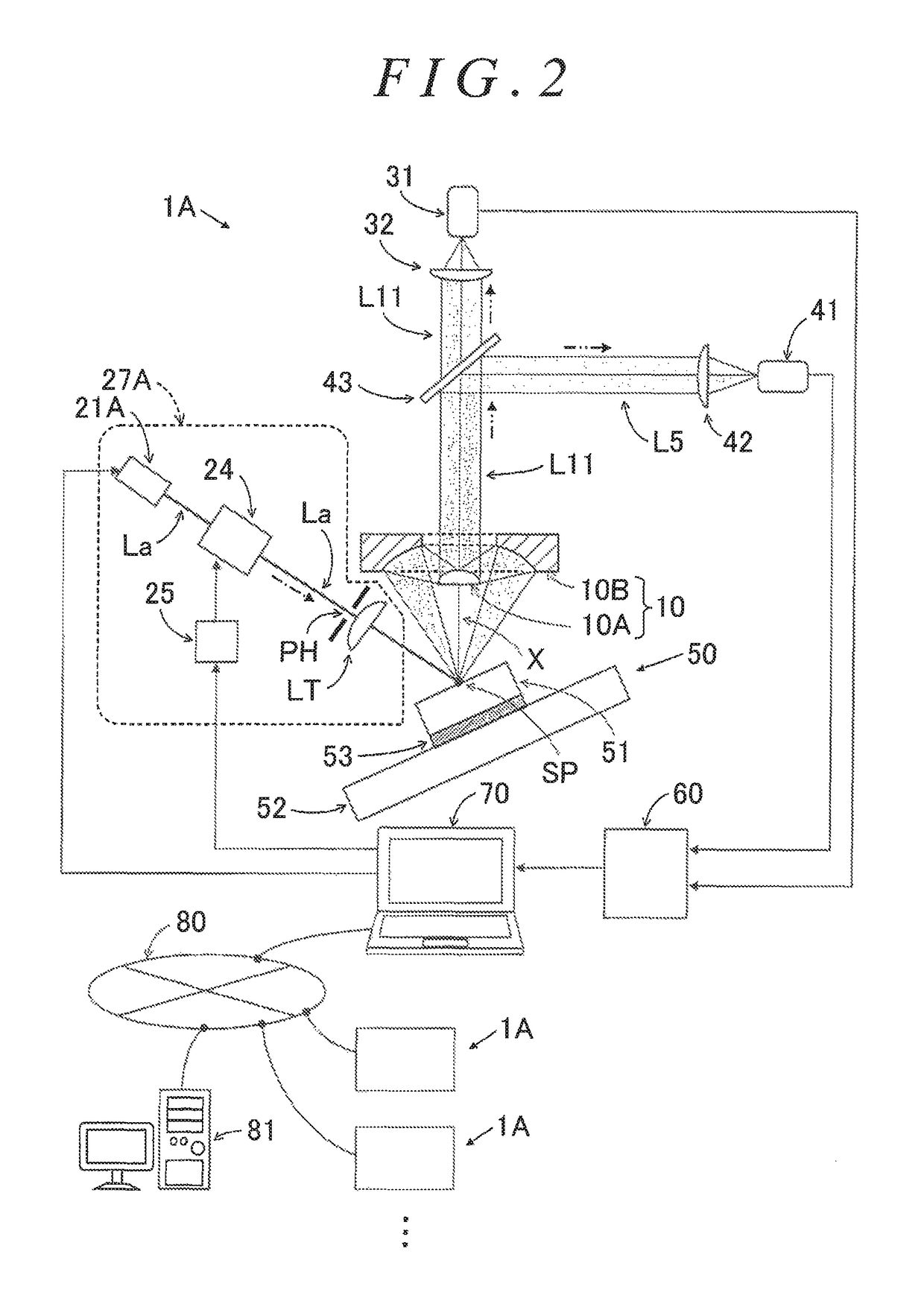
[0024]Embodiments of the invention will be described below with reference to the accompanying drawings. An optical nondestructive testing apparatus 1 according to a first embodiment of the invention and an optical nondestructive testing apparatus 1A according to a second embodiment of the invention described below each determine a connection area between connection interfaces of a first member 51 and a second member 52 of a measurement object 50. The first member 51 and the second member 52 are connected to each other with solder 53. The optical nondestructive testing apparatus 1 and the optical nondestructive testing apparatus 1A each apply a heating laser to a measurement point SP on the surface of the first member 51 of the measurement object 50. The intensity of the heating laser changes sinusoidally. The optical nondestructive testing apparatus 1 and the optical nondestructive testing apparatus 1A each determine the connection area between the connection interfaces of the first...


PUM


Abstract

An optical nondestructive testing method includes: a laser emitting step involving emitting a heating laser from a laser output device such that the intensity of the heating laser applied to a measurement point changes sinusoidally; a laser intensity measuring step involving measuring the intensity of the heating laser by a phase difference detector; an infrared radiation intensity measuring step involving measuring, by the phase difference detector, the intensity of infrared radiation radiating from the measurement point; a phase difference measuring step involving determining, by the phase difference detector, a phase difference between the intensity of the heating laser and the intensity of the infrared radiation, and outputting the phase difference determined to a determiner from the phase difference detector; and a connection area calculating step involving determining, by the determiner, a connection area in accordance with the phase difference and phase difference-connection area correlation information.

Description

INCORPORATION BY REFERENCE[0001]The disclosure of Japanese Patent Application No. 2016-004217 filed on Jan. 13, 2016 including the specification, drawings and abstract is incorporated herein by reference in its entirety.BACKGROUND OF THE INVENTION[0002]1. Field of the Invention[0003]The invention relates generally to optical nondestructive testing methods and optical nondestructive testing apparatuses. More particularly, the invention relates to an optical nondestructive testing method and an optical nondestructive testing apparatus that optically nondestructively determine a connection area between connection interfaces of a first member and a second member of a measurement object connected to each other directly or connected to each other with a connector interposed therebetween.[0004]2. Description of the Related Art[0005]In recent years, first and second members made of various materials have been connected to each other, creating a demand for testing the state of connection bet...

Claims


Application Information

Patent Timeline
Patent Type & Authority Patents(United States)
IPC IPC(8): G01J5/00G01J5/52
CPCG01J5/0096G01J5/52G01J5/0007G01J2005/528G01N25/72
Inventor MATSUMOTO, NAOKIYOSHIDA, KOUYAUMEZAWA, RYOTAMATSUMOTO, JUN
Owner JTEKT CORP
Features
  • R&D
  • Intellectual Property
  • Life Sciences
  • Materials
  • Tech Scout
  • Unparalleled Data Quality
  • Higher Quality Content
  • 60% Fewer Hallucinations
Learn More