Bone cleaning assembly with a rotating cutter that is disposed in a rotating shaving tube that rotates independently of the rotating cutter

a cleaning assembly and rotating cutter technology, applied in the field of rotating cutters, can solve the problems of surgical personnel's skin coming into direct contact with the bone, the surgical personnel's sharp cutting tools being used to cut or tear through gloves, and the gloves worn by the surgical personnel's hands, so as to reduce the need for manual grasping and bone cleaning.

Active Publication Date: 2018-07-31
STRYKER CORP
View PDF13 Cites 1 Cited by
  • Summary
  • Abstract
  • Description
  • Claims
  • Application Information

AI Technical Summary

Benefits of technology

This patent describes an assembly for cleaning bone stock. The assembly includes a shell with a void space for holding the bone stock, a cutter for removing soft tissue from the bone stock, and a guide for moving the bone stock towards the cutter. Another assembly includes a shell, a cutter, and a shaving tube that can rotate at different speeds or directions relative to the cutter. The technical effect of this invention is to provide a more efficient and effective way to clean bone stock by removing soft tissue and debris without damaging the bone or compromising its quality.

Problems solved by technology

Moreover, to perform the cleaning process, the surgical personnel may need to firmly grasp the bone.
Exerting such force on the bone may cause tearing of the gloves worn by the surgical personnel.
Furthermore, the sharp cutting tools being used by the surgical personnel could cut or tear through the gloves.
Such cutting or tearing through the gloves could result in the possibility that skin of the surgical personnel may come into direct contact with the bone.
This contact can result in contamination of the bone.

Method used


Image

  • Bone cleaning assembly with a rotating cutter that is disposed in a rotating shaving tube that rotates independently of the rotating cutter
  • Bone cleaning assembly with a rotating cutter that is disposed in a rotating shaving tube that rotates independently of the rotating cutter
  • Bone cleaning assembly with a rotating cutter that is disposed in a rotating shaving tube that rotates independently of the rotating cutter

Examples


Embodiment Construction

I. Assembly

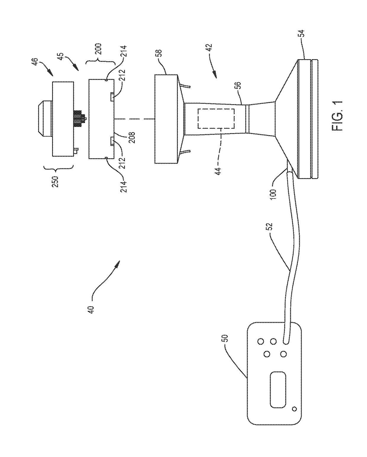
[0067]Referring to the Figures, a bone cleaning system for cleaning bone stock is generally shown at 40 in FIG. 1.

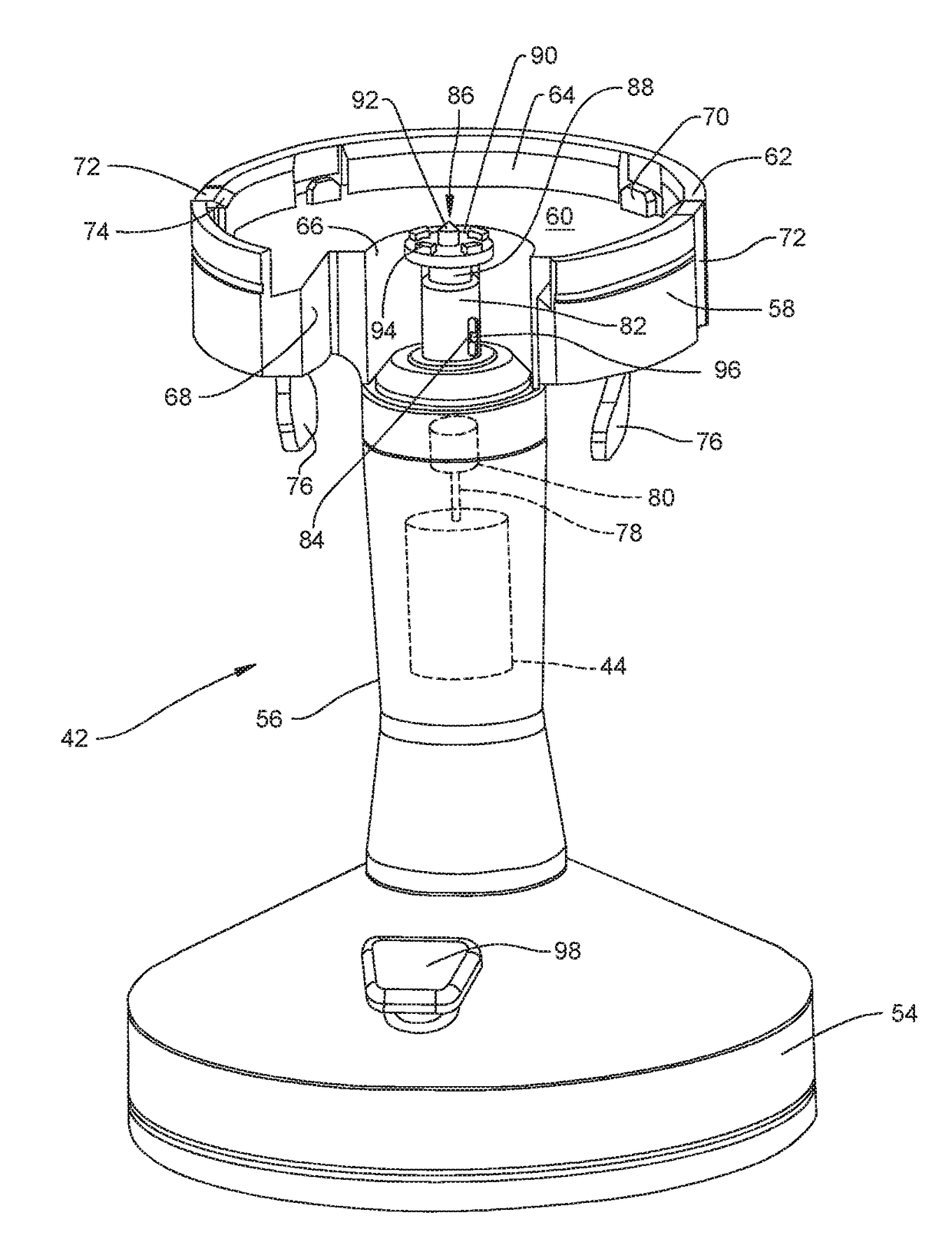
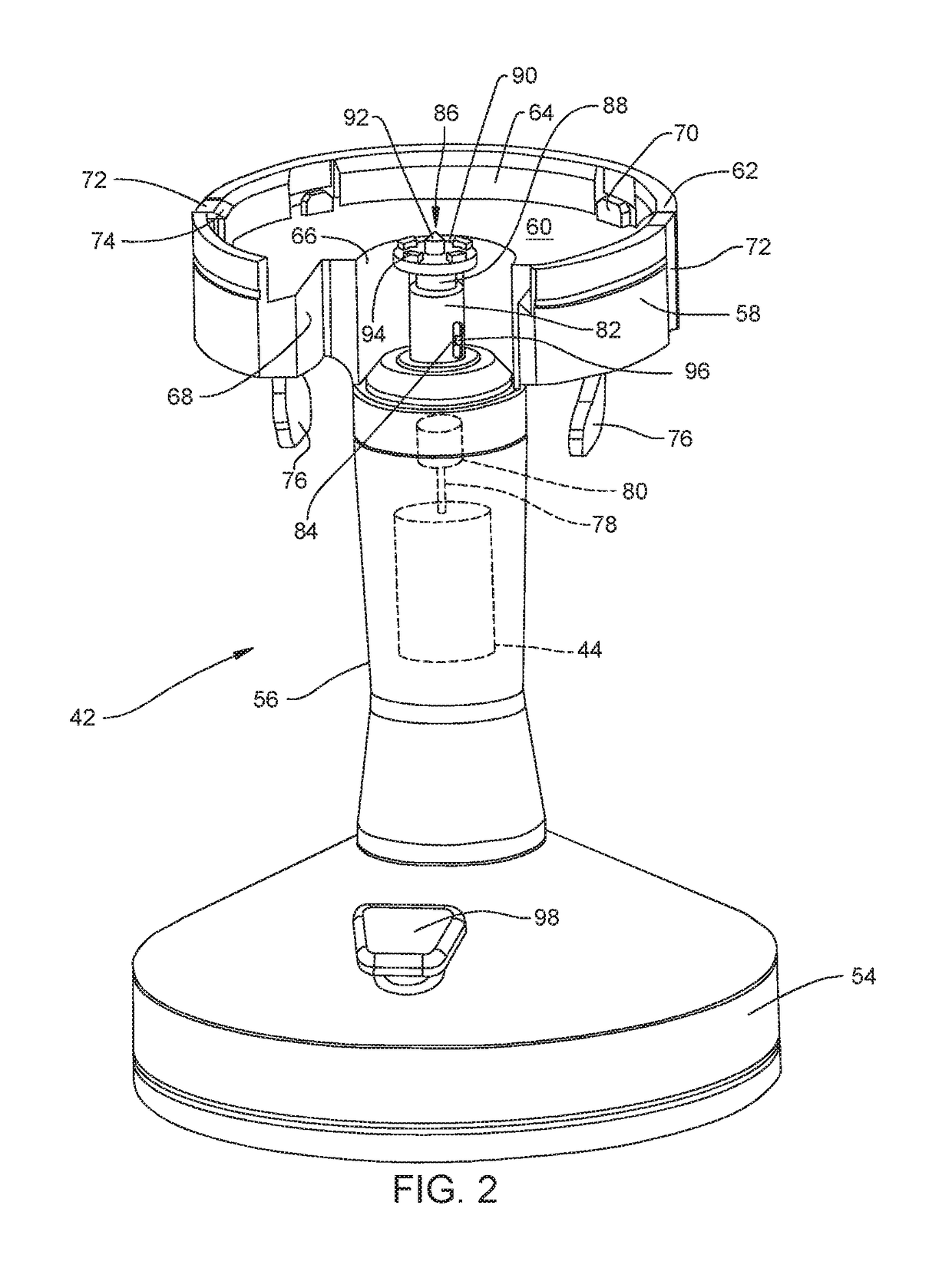
[0068]System 40 includes a base unit 42. Internal to the base unit 42 is a drive motor 44. A drive module 45 is configured to be removably attachable to the base unit 42 for coupling to the motor 44. A cleaning module 46, for cleaning bone stock, is removably attachable to the drive module 45. In the embodiment shown, the base unit 42 and drive module 45 are reusable, while the cleaning module 46 is disposable for discarding after the bone stock is cleaned.

[0069]The cleaning module 46 includes at least one cutter 48 for cutting soft tissue from bone stock (see FIGS. 4 and 7). Cleaning module 46 is configured so that, when attached to the drive module 45 positioned on base unit 42, cutter 48 is operatively connected to the motor 44 though the drive module 45 so as to be actuated by the motor 44.

[0070]Harvested bone stock is placed in the cleaning module 46. The...


PUM


Abstract

A cleaning module for cleaning bone stock used in surgical procedures. The cleaning module includes a shell. The shell defines a void space to receive the bone stock. A cutter is rotating mounted in the void space. A shaving tube, also able to rotate, is coaxially disposed about the cutter. The cutter and shaving tube have complementary edges. A drive assembly rotates the cutter and shaving tube at different speeds, at different times or in different directions relative to the cutter. As a result of the rotation of the cutter and shaving tube soft tissue adhering to the bone stock is cut away from the bone stock by the relative rotating of the cutting edges of the cutter and shaving tube.

Description

RELATIONSHIP TO EARLIER FILED APPLICATIONS[0001]This application is a divisional of U.S. patent application Ser. No. 14 / 311,674 filed 23 Jun. 2014 now U.S. Pat. No. 9,687,361. U.S. patent application Ser. No. 14 / 311,674 is a continuation of PCT Pat. App. No. PCT / US2012 / 072160 filed 28 Dec. 2012. PCT App. No. PCT / US2012 / 072160 is a non-provisional application that claims priority from U.S. Prov. Pat. App. No. 61 / 581,310 filed 29 Dec. 2011. The contents of the above-identified applications from which this application claims priority are incorporated herein by reference.FIELD OF THE INVENTION[0002]This invention relates to an assembly able to clean bone stock for use in surgical procedures.BACKGROUND OF THE INVENTION[0003]In certain surgical procedures chip-sized bone is used as filler adjacent intact bone. For example, in a spinal fusion procedure, it is known to place a compound formed out of milled bone chips around implanted rods. The rods hold adjacent vertebrae in alignment. This...

Claims


Application Information

Patent Timeline
Patent Type & Authority Patents(United States)
IPC IPC(8): A61B17/16A61F2/46
CPCA61B17/1635A61F2/4644A61F2002/4646
Inventor LYNCH, ROBERT E.DIEHL, ERIC K.HORTON, IV, JOHN COLEMANKEILERS, CYRIL A.BERNERO, JOHN P.
Owner STRYKER CORP
Why Eureka
Try Eureka