Automated control of toolface while slide drilling

a tool face and automatic control technology, applied in the direction of apparatus for force/torque/work measurement, wellbore/well accessories, survey, etc., can solve the problems of slowing down drilling, and increasing friction between the drill string and the borehol

Active Publication Date: 2018-07-31
NABORS DRILLING TECH USA INC
View PDF15 Cites 21 Cited by
  • Summary
  • Abstract
  • Description
  • Claims
  • Application Information

AI Technical Summary

Problems solved by technology

Friction between the drill string and the bore generally increases as a function of the horizontal component of the bore, and slows drilling by reducing the force that pushes the bit into new formations.
Although change of the borehole direction is typically accomplished through a gradual deflection over hundreds of feet or more so that the drill string bends gradually, the friction between the drill string and the borehole generally increases.
These methods can be slow due to transmission speed of receiving the appropriate downhole data at the surface.
Reorienting the toolface in a bore can be very complex, labor intensive, and often inaccurate, and thus, automated methods and systems are desired.

Method used


Image

  • Automated control of toolface while slide drilling
  • Automated control of toolface while slide drilling
  • Automated control of toolface while slide drilling

Examples


Embodiment Construction

[0012]It is to be understood that the following disclosure provides many different embodiments, or examples, for implementing different features of various embodiments. Specific examples of components and arrangements are described below to simplify the present disclosure. These are, of course, merely examples and are not intended to be limiting. In addition, the present disclosure may repeat reference numerals and / or letters in the various examples. This repetition is for the purpose of simplicity and clarity and does not in itself dictate a relationship between the various embodiments and / or configurations discussed.

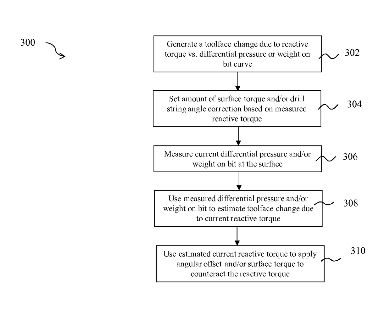
[0013]The present disclosure provides systems and methods that proactively control toolface orientation by using surface standpipe pressure and / or weight on bit (WOB) readings to estimate changes in toolface, due to reactive torque. In particular, reactive torque is predicted based on surface readings, and in one embodiment is predicted based on surface readings withou...


PUM

PropertyMeasurementUnit
lengthaaaaaaaaaa
pressureaaaaaaaaaa
surfaceaaaaaaaaaa

Abstract

Apparatuses, systems, and methods for controlling slide drilling on a drilling rig are described. The methods include detecting current differential pressure of a mud motor and / or weight on bit (WOB) at a surface of a borehole, predicting current reactive torque of the mud motor based on the current differential pressure and / or WOB, and automatically adjusting surface torque and / or angular offset of a tubular adjacent the surface to counteract the current reactive torque and to keep the mud motor at a desired toolface orientation in the borehole.

Description

TECHNICAL FIELD[0001]The present disclosure relates to apparatuses, systems, and methods for directional drilling, and more specifically sliding with a downhole mud motor.BACKGROUND OF THE DISCLOSURE[0002]Subterranean “sliding” drilling operation typically involves rotating a drill bit on a downhole motor at the remote end of a drill pipe string during a drilling operation. Drilling fluid forced through the drill pipe and downhole motor rotates the drill bit. The assembly is directed or “steered” from a vertical drill path in any number of directions, allowing the operator to guide the wellbore to desired underground locations. For example, to recover an underground hydrocarbon deposit, the operator may drill a vertical well to a point above the reservoir and then steer the wellbore to drill a deflected or “directional” well that penetrates the deposit. The well may pass horizontally through the deposit. Friction between the drill string and the bore generally increases as a functio...

Claims


Application Information

Patent Timeline
Patent Type & Authority Patents(United States)
IPC IPC(8): G01L5/00E21B47/024E21B44/00E21B49/00E21B7/06
CPCG01L5/0004E21B7/068E21B49/003E21B47/024E21B44/005
Inventor FISHER, JR., GARY VERDEANHUNTER, GRAHAMHADI, MAHMOUDROLONG, CARLOS
Owner NABORS DRILLING TECH USA INC
Why Eureka
Try Eureka