De-icing of a wind turbine blade

a wind turbine blade and blade technology, applied in the direction of machines/engines, sustainable transportation, mechanical equipment, etc., can solve the problems of reducing blade life, increasing root load, and reducing power production, so as to achieve the effect of effective de-icing of the aerodynamically important part, minimizing the additional weight of the structure, and great beneficial effect of blade torqu

Active Publication Date: 2018-08-07
VESTAS WIND SYST AS
View PDF22 Cites 3 Cited by
  • Summary
  • Abstract
  • Description
  • Claims
  • Application Information

AI Technical Summary

Benefits of technology

[0010]The underlying principle involves the use of hot air applied to the blade so as to heat of a surface of the blade and consequently de-ice the surface. In particular, the hot air may be applied to a portion of the blade adjacent to the leading edge of said blade. In a still further embodiment, hot air may be applied to the blade adjacent to both the leading edge and the trailing edge. Ice that is removed from the leading edge may migrate around the blade and re-freeze on the trailing edge. By providing hot air to the trailing edge, this migrating ice may be prevented from re-freezing and so prevented from re-forming.
[0012]Alternatively, each orifice may be connected to a duct for directing the flow of hot air to a specific portion of the blade, such as adjacent to a leading edge of the blade, should it be desired to concentrate the heat at that point for maximum effect. Further, the hot air may be directed to the leading edge, on the basis that de-icing a first third of the blade span, that is that third of the blade measured from the blade point, may have the greatest beneficial effect on torque generated by the blade. In this way, the additional weight of the structure may be minimized, while still ensuring effective de-icing of the aerodynamically important part of the blades. Such a concentration of hot air on a portion of the blade, such as the final third of the leading edge may be a thermally efficient method for de-icing, and may assist in providing a uniform heating zone and so avoiding cold spots which may not effectively remove said ice.
[0013]Such an arrangement may lead to a short heating time and low power output. It may also allow heating when the blades are stationery or moving, which may prevent down time of the wind turbine generator. It may also allow either continuous heating which may act as a preventive measure or intermittent heating when required.

Problems solved by technology

Ice accretion on wind turbine blades causes:Change in aerodynamic shape resulting in significantly reduced power productionIncreased root loads and reduced blade lifeUnbalanced mass on the rotor planeDanger of ice throw from the blades

Method used


Image

  • De-icing of a wind turbine blade
  • De-icing of a wind turbine blade
  • De-icing of a wind turbine blade

Examples


Embodiment Construction

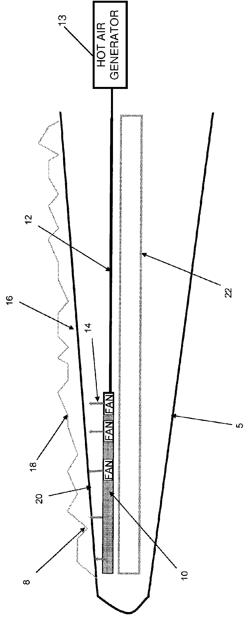
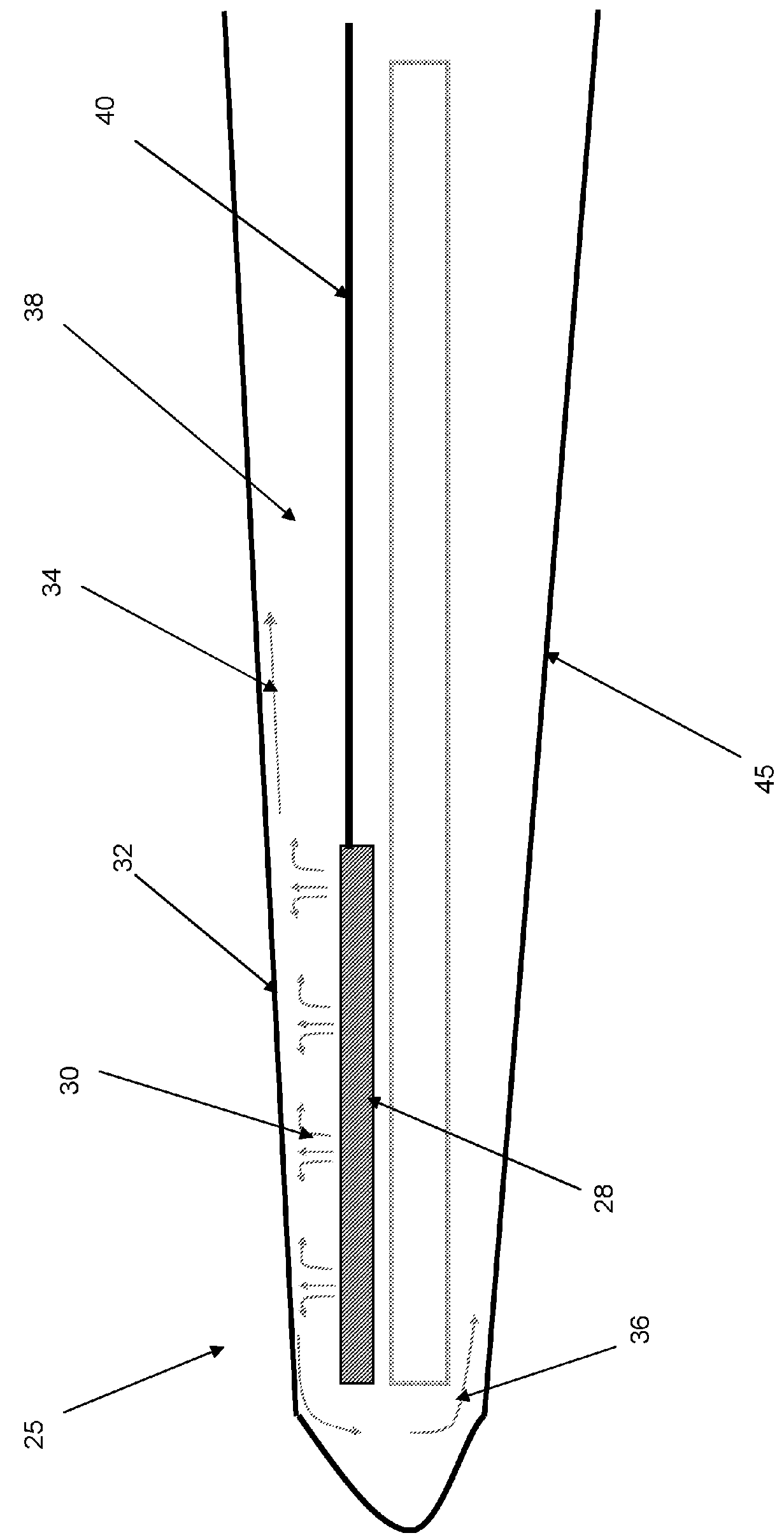
[0021]FIG. 1 shows a wind turbine generator blade 5 in cross section. The blade 5 includes a spar 22 to provide Structural support for the blade and mounted to it is a heat reservoir 10 for receiving a flow of hot air through an insulated duct 12. Said duct 12 is connected to a hot air generator 13, for instance a fan or pump flowing air across a heating element. Alternatively, waste energy from the wind turbine generator, such as within the nacelle, may also provide a source of heat.

[0022]Projecting from the heat reservoir 10 is a plurality of ducts 14 delivering hot air to a leading edge 20 of the blade. In so doing, the hot air heats the leading edge 20 sufficiently to allow the removal of ice 18 that has formed over the leading edge, through to partially melting and falling away from the blade so as to better provide performance.

[0023]Under freezing conditions, an accretion of ice 18 may build up on the leading edge of the blade so as to change the shape as well as add mass in a...


PUM


Abstract

A heating assembly for a blade of a wind turbine generator, the heating assembly comprising: a heat reservoir positioned within a cavity of the blade, the heat reservoir in communication with a heat source; the heat reservoir including a plurality of orifices for venting hot air from the heat reservoir.

Description

FIELD OF THE INVENTION[0001]The invention relates to wind turbine generators (WTG's) used in the generation of electricity. In particular, the invention relates to means of removing ice from a rotor blade of a wind turbine generator.BACKGROUND[0002]Blade de-icing is critical in WTG because there is a 20% to 50% increase in the loss production factor. Ice accretion on wind turbine blades causes:[0003]Change in aerodynamic shape resulting in significantly reduced power production[0004]Increased root loads and reduced blade life[0005]Unbalanced mass on the rotor plane[0006]Danger of ice throw from the blades[0007]In the case of melting ice, the principal characteristic is the surface-ice interface temperature which has to be above freezing. When melting occurs at the blade surface-ice interface, chunks of ice fall off as a result of wind and gravity forces.[0008]The amount of heat and the time required to melt the ice depends on numerous factors. These include the thickness of the ice ...

Claims


Application Information

Patent Timeline
Patent Type & Authority Patents(United States)
IPC IPC(8): F01D5/08F03D80/40
CPCF03D80/40F05B2260/20Y02T50/675Y02E10/72Y02T50/60
Inventor BAHUGUNI, ANANDKANDASAMY, RAVIWONG, VOON HON
Owner VESTAS WIND SYST AS
Why Eureka
Try Eureka